Peak Smoothing
FEM-Design defines peak smoothing regions to solve possible singularity problems. These are regions in active zones in the environment of the singularity, where the inner forces change substantially, as a result of mesh refinement.
Peak smoothing regions can be generated automatically by the mesh generator or calculation processes. Automatic generation always results in circular peak smoothing regions, with centre points placed in the location of the singularity. The radius of a circular smoothing region depends on the geometry of the singularity locations.
Singularity Problem
As an effect of the mesh refinement, the calculated results are converging to the theoretical solution. The problem is that at certain places we get infinite inner forces according to the theory, so the inner forces increase each time by refining the mesh.
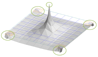
These places could be: point supports, endpoints of edge supports, vertices of surface supports, endpoints of beams and columns, endpoints of intersection lines of adjoining surfaces, point loads, endpoints of line loads, vertices of surface loads etc. In practice, usually, the singularity problem occurs at supports because they heavily influence the inner forces (e.g. negative moments) in ratio.
Why wait? Download an automated 2 x week free trial of FEM-Design and get started today!
Calculations performed according to:
Euro Code
Belgian National Annex
British National Annex
Danish National Annex
Dutch National Annex
Estonian National Annex
Finnish National Annex
German National Annex
Hungarian National Annex
Latvian National Annex
Norwegian National Annex
Polish National Annex
Romanian National Annex
Spanish National Annex
Swedish National Annex
Turkish Seismic Code
Languages supported:
English
Finnish
French
Dutch
Hungarian
Polish
FEM-Design Wiki
For more details on the Peak Smoothing theory please visit the FEM-Design Wiki by clicking here.
FEM-Design Blog
StruSoft participates at Nordbygg
We are delighted to announce that StruSoft will be present at Nordbygg, one of the most prominent events for the building and construction industry [...]
FEM-Design v21 Release News
FEM-Design v21 was released on 26th January 2022 and includes many brand new features, as well as significant number of improvements in all areas [...]
How to make a Stringer Panel Model in FEM-Design
A few years ago our now CEO, Dennis Kristensen, made a Stringer Panel Model webinar using our FEM Design software for Structural Concrete Design [...]
