


IDEA StatiCa Connection
StruSoft offers a brand new tool that enables a smart connection between FEM-Design and IDEA StatiCa. The tool allows for sending 3D steel structures, or even just selected connected members and their internal forces as intelligent input for detailed design and verification of steel connections between FEM-Design and IDEA StatiCa.
This dedicated tool accelerates the finalization, detailing and documentation of steel connections thanks to IDEA StatiCa’s 250 ready connection templates and more than 10,000 configurations, as well as the optimization of fabrication and raw material costs.
Key features
- Sharing FEM-Design data with IDEA StatiCa as an input for steel connection design including:
- positions, cross-sections and materials of steel bar members,
- internal forces (normal, shear forces and moments) calculated in the members.
- Option to select which connected steel members shall be transferred to IDEA StatiCa.
- Data transfer can be done in two simple ways:
- via a live, direct link, if both programs are available on the computer, or
- via a dedicated file, if the two programs are running on separate computers.
- In case of the live connection, a single click updates the input of the IDEA StatiCa connection design based on changes in the linked FEM-Design model.
- Automatic, but editable data matching (cross-section and material) between the two programs.
- Installation of any additional programs on either side is not required.

Limitations
Connection design in IDEA StatiCa works only for straight and uniform bars.
Compatibility
- FEM-Design 22 and later version
- IDEA StatiCa 21.0 and later version
FEM-Design model-preparation
Following model preparations must be made in FEM-Design before export to IDEA StatiCa.
Run analysis for Load cases or Load combinations
Run analysis on the FEM-Design model containing steel bar elements:
- If linear calculation is suitable, run Calculate > Static and stability analysis > Load cases.
- If non-linear calculation is necessary, choose Calculate > Static and stability analysis > Load combinations and set non-linear options at Setup by load combinations.
Note: In case of linear calculations only, load case results are exported, because IDEA StatiCa can calculate load combination results and perform connection design for them.

Define Joints
Specify the bar connections / nodes that shall be designed in IDEA StatiCa. In Steel design > Steel joint mode, use the Define joint command and create the connections using the General joint function made for the IDEA StatiCa connection. The image below shows an example where joints have been defined at all bar ends.

Notes
- Since IDEA StatiCa’s connection design works only for straight and uniform bars, the joints belonging to the bar ends are automatically deleted once the geometry of a bar is changed to a curved axis or varying cross-section.
- Regular FEM-Design Steel joints can also be exported to IDEA StatiCa.
Transfer of FEM-Design model to IDEA StatiCa
Transfer of joints, steel members and results between FEM-Design and IDEA StatiCa can be done in two ways:
- via a live, direct link – if both programs are available on the computer, or
- via a dedicated file, if the two programs are running on separate computers.
Notes
- The export process must be started from Steel design mode, where steel joints are visible and ready for selection by default. In other modes, the Steel joint, symbol layer must be activated, for the joints to be selected.
- In both cases, it is possible to decide if all joints shall be transferred, or only selected.
- Steel material and cross-section mapping between the programs is based on an editable template file: C:\Users\USERNAME\AppData\Roaming\StruSoft\FEM-Design VERSION\FEMData\saf_export_mappings.xlsx
- Unmatched FEM-Design cross-sections are assigned with a parametric description, based on which IDEA StatiCa creates the sections.
Direct (live) link
With this method, the FEM-Design export creates an IDEA StatiCa project that is ready to start working with and designing the transferred joints. The workflow is as follows:
In FEM-Design:
1. Save the current project before data transfer.
2. Run the command Export to / IDEA StatiCa – Checkbot.
3. Select the joints to be exported to IDEA StatiCa.
4. Select the version of the IDEA StatiCa.
5. Set the IDEA StatiCa project name. By default, the name of the current FEM-Design project (saved in the first step) is offered, but it is not mandatory to use it. The data structure of a new IDEA StatiCa project is created in the subfolder with its name within the folder of the current FD project.
6. Click the OK button and the IDEA StatiCa Checkbot will start.

In IDEA StatiCa Checkbot:
7. If the specified IDEA StatiCa project does not exist yet, one must approve its creation by pressing the Create project button in Checkbot’s New project dialog. Otherwise, an already existing project will be opened automatically.

8. Press the Connections button (Import tab) in order to load data exported from FEM-Design.

Note: In IDEA StatiCa – in the bottom right corner – the following “connection” symbol indicates that the program maintains a live link with FEM-Design. This is important for later synchronization of data. If the link is broken (for example, a program is closed), reviving the live link requires a simple repeat of the export (see Data synchronization).

File exchange
With this method, FEM-Design saves the data required for the design of selected joints in a SAF (.xlsx) file, which IDEA StatiCa Checkbot can read and easily use to build the connection design project. The workflow is as follows:
In FEM-Design:
1. Run the command Export to / IDEA StatiCa – File.
2. Select the Joints to be designed with IDEA StatiCa.
3. Save the file with a specific name and location.

In IDEA StatiCa Checkbot:
4. Create a new IDEA StatiCa project at New.
5. Open the file saved with FEM-Design using the SAF command (Import tab).


Detailed connection design (briefly)
Upon finishing the transfer process, the selected objects from FEM-Design are immediately displayed on the Checkbot interface. Here, use the following tools in order to display additional data:
- Members and Connections (Labels) for displaying the identifiers of the objects specified in FEM-Design,
- Member 1D Forces for displaying the internal force diagrams showing the calculation results of FEM-Design.

Design the connections one by one with the IDEA StatiCa Connection:
1. Use the Open command in order to send the connection to the Connection module.

2. Specify how each member is connected to each other and with what design type.

3. Set the parameters, the sizes, the positions, and the behaviors of the assembly components such as plates, bolts and welds.

4. Analyze, check and optimize the connection until it meets the requirements. Finally, document the finalized connection type in detail.

Data synchronization
In case of a live FEM-Design – IDEA StatiCa link, there are two methods to synchronize model data changes:
A. If we want to add new connections (joint and members) from the FEM-Design model to a project already shared with IDEA StatiCa, we must apply the following steps:
- Export to IDEA StatiCa Checkbot: In FEM-Design select and export the joints including the new ones and choose the existing project name at the export settings.
- Import with Checkbot: Click the Connections function, and the new items and data are loaded.
B. If the list of previously shared joints (connections) to be tested does not change, only their position or the material/cross-section/properties of the connecting bars or the loads, then there is no need to repeat the export, the new data will be automatically synchronized by clicking the Sync button (Structural model) in Checkbot (see the next image).
Notes
- In both cases the update only works if the FEM-Design results are valid, so analysis should run after the model changes.
- If the connection between FEM-Design and Checkbot is lost/broken, or if we want to reopen the IDEA StatiCa project associated with the current FEM-Design project, use the IDEA StatiCa – Relink function (File > Export to). In the case of connections older than version 23 of FEM-Design, method A must be used for restarting the connection. In this case it is sufficient to select only one joint during the re-export.
- Relink will only work if the corresponding FEM-Design (.str) project for the IDEA StatiCa project is also saved. Before synchronizing model or calculation changes with IDEA StatiCa, it is recommended to save the current project states in FEM-Design (.str) as well.

Why wait? Download an automated 2 x week free trial of FEM-Design and get started today!
FEM-Design Wiki
Full details on the IDEA StatiCA connection can be found on the FEM-Design Wiki by clicking here.
Calculations performed according to:
FEM-Design performs all structural calculations to Eurocode standards, with support for 15 National Annexes across Europe. Whether you’re designing in Denmark, Netherlands, Poland or the UK, FEM-Design ensures full compliance with your local requirements.
 Eurocode
- Belgian Annex
- British Annex
- Danish Annex
- Dutch Annex
- Estonian Annex
- Finnish Annex
- German Annex
- Hungarian Annex
- Latvian Annex
- Norwegian Annex
- Polish Annex
- Romanian Annex
- Spanish Annex
- Swedish Annex
Languages supported:
- English
- Finnish
- French
- Dutch
- Hungarian
- Polish
2nd Generation Eurocode under development

FEM-Design Blog
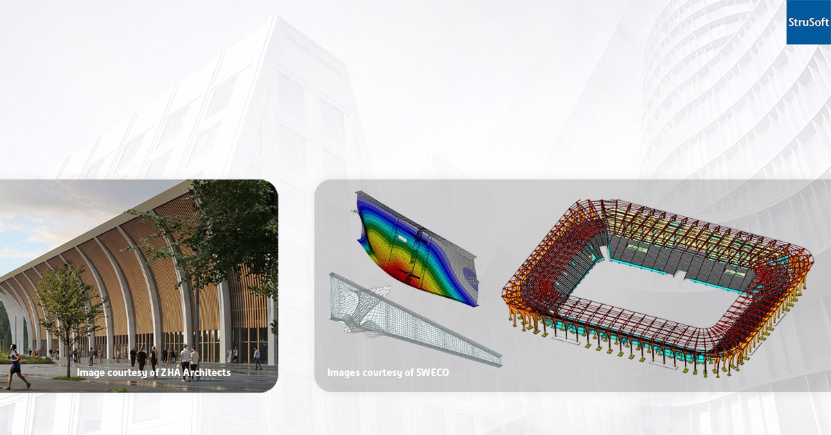
New Aarhus Stadium: FEM-Design Optimises Steel Girders and Precast Columns
The New Aarhus Stadium, a 24,000-seat venue in Denmark’s second-largest city, represents a bold fusion of engineering precision and architectural expression. Inspired by the [...]
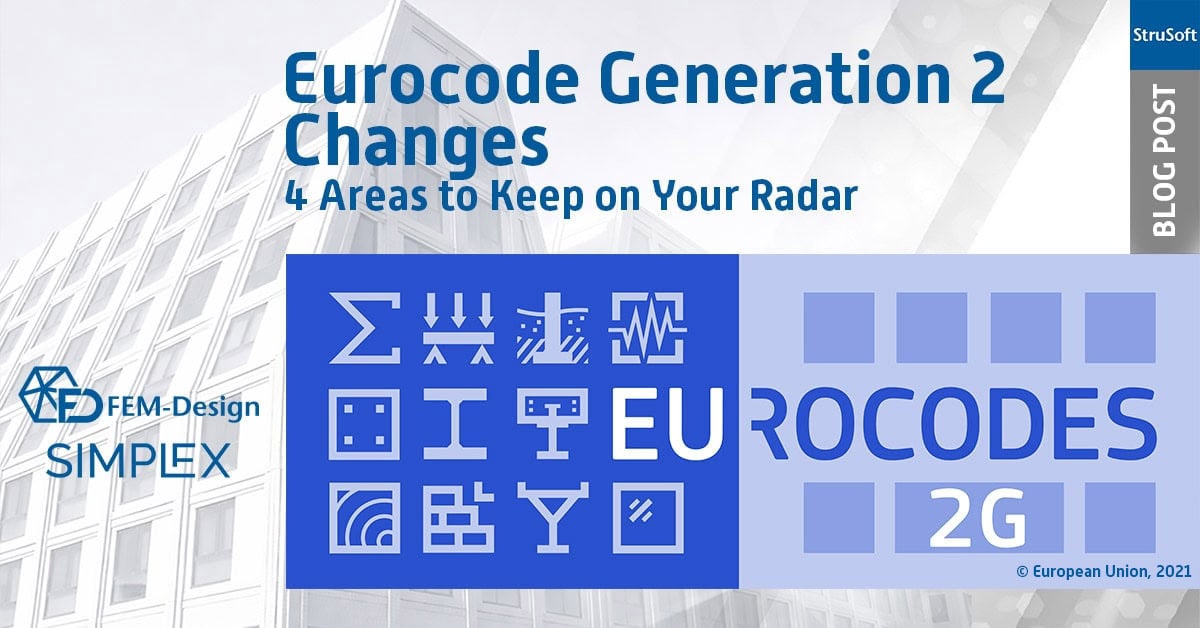
Eurocode Generation 2 Changes: 4 Areas to Keep on Your Radar
The Eurocode generation 2 changes don’t represent a complete overhaul, but they do introduce meaningful shifts in how we model structural behaviour. Many of [...]
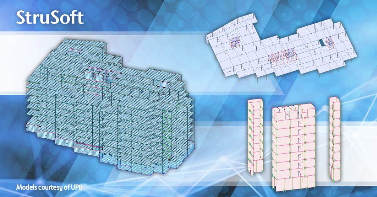
FEM-Design Powered UPB’s Structural Analysis for a 9-Storey Office Building in Oslo
Frederik Selmers vei 2, a major office development in Oslo, Norway, required an advanced structural analysis to gain realistic diaphragm behaviour, detailed representation of [...]

Bio: Panos has worked for over 5 years as a structural engineer before joining StruSoft in 2025, using WIN-Statik and FEM-Design in his daily practise. Panos ...show more understands the practical needs of todays customers and will help them solve their daily problems with any StruSoft software. Feel free to contact Panos if you need any technical assistance or would like a training or a demo of our structural software. show less

Bio: Mikkel is responsible for the sales of all our structural software in Denmark. With a background in civil engineering and hands-on experience using FEM-Design for ...show more large-scale projects, he understands the challenges engineers face. Mikkel’s goal is to help Danish companies find the right structural software solutions to optimize their projects and meet their specific needs. show less

Bio: Joni has helped and trained hundreds of engineers in structural analysis in Finland. He works in both civil and mechanical engineering fields with structural analysis. ...show more Joni has over 15 year of experience in structural design of many types and sizes of steel, concrete and timber structures. Joni is the Product Owner of our JIGI software and Country Manager for Finland. Please free to contact Joni if you need any help to solve your structural analysis problems. show less

Bio: Marek Krawczyk is the Country Manager for Poland at StruSoft. As a structural engineer, he has more than ten years of international experience, working on ...show more various projects in Europe, the UK, the USA and Asia. He joined StruSoft in 2022 to strengthen our presence in Poland and support the StruSoft software Users in the local market. show less

Bio: Ciprian Tibea is the Sales Manager for Baltics & Romania and has been with StruSoft since 2018. Ciprian has a PhD in Civil Engineering (Ultra ...show more High Performance Concrete Subjected to Shear Action) and a Masters Degree in Entrepreneurship and Business Administration. Prior to StruSoft, Ciprian was working as a research engineer for Consolis for 6 years and for 1 year with a local company in Romania working on structural design projects with advanced Finite Element Software (Diana and Atena). Ciprian is your main Structural Sales contact for markets outside Europe, the Baltics and Romania. Please feel free to get in touch. show less

Bio: Mohsen Ghaemi is the Hungarian Manager for StruSoft in our Structural Business Unit. He has a PhD in Structural Civil Engineering (Topology optimisation). Mohsen has ...show more been with StruSoft since 2002 and has more than 20 years of experience with the FEM-Design software and its development, as well as in customer relationships and sales. Please feel free to get in touch with Mohsen directly. show less

Bio: Victor is Customer Success Engineer at Strusoft situated at our Gothenburg office where he works in close contact with our customers to help them use ...show more our software in the best way possible. He has a background as a structural engineer with many years of hands-on experience of using FEM-Design and WIN-Statik in his day-to-day work for large and small projects alike. Please feel free to contact Victor if you need guidance in FEM-Design, are interested in a demonstration or have any general questions. show less

Bio: Jan Wróbel has over 6 years prior experience before joining StruSoft working as a structural engineer, using FEM-Design and WIN-Statik in his daily practice. His ...show more international project work has equipped him with broad technical knowledge and understanding of various design standards and client needs. He is now focusing on technical support for Polish customers. Feel free to contact Jan for any assistance with StruSoft's structural software or any other structural engineering questions! show less

Bio: Markus Mitikka is a customer coach for StruSoft in Finland. He has previous experience of FEM calculations and structural designs working for engineering office. He ...show more was a big fan of StruSoft software before joining StruSoft in beginning of 2022. Markus can help you to become more efficient with all our structural software. Please feel free to get in touch. show less

Bio: Casper Hougaard is Owner of Market & User Value for FEM-Design, and Product Owner for PREFAB. He joined StruSoft in 2022 and has a background ...show more in civil engineering with lots of practical experience using FEM-Design. Casper helped hundreds of customer as a Customer Success Engineer in Denmark before transitioning to the development department. show less

Bio: Fredrik Lagerström MSc has 8 years prior experience before joining StruSoft working as a civil engineer using FEM-Design, WIN-Statik & PRE-Stress in his daily practice. ...show more In 2011 Fredrik joined StruSoft as a Technical Sales and Education Manager. Fredrik works closely with both Sales and Development to get feedback directly from our Swedish Customers to in turn help our Developers to implement the requested new features in an accurate way. Please feel free to get in touch with Fredrik if you require any technical help or support with our structural software. show less

Bio: Shahram Omary is an account manager at Matrix Software, the Dutch affiliate of StruSoft, specializing in structural software solutions for the Dutch construction sector. With ...show more a strong technical foundation in civil engineering and a master’s degree in Construction Management and Engineering from TU Delft, Shahram combines academic insight with practical industry experience. His background spans roles in design, preparation/planning, and engineering consultancy firms. Shahram is passionate about digitalization and innovation in structural design, striving to deliver tailored software solutions that align with clients' technical and business goals. Currently, he is responsible for market strategies based on market analyses in the Dutch market. In parallel, he also contributes to the marketing aspects related to the current promotion of the software packages, including FEM-Design, in collaboration with the marketing team. show less


Bio: Botond Előd Nagy is a Structural Civil Engineer focusing on professional and academic education, with a strong emphasis on innovative, technology-driven solutions.

Bio: Tobias has 4 years of experience as a structural engineer working a lot with prefabricated concrete elements from a consulting firm in Denmark. His mission ...show more at StruSoft is clear: to help our customers solve real-world challenges using our structural software. show less

Bio: Suhas is the Managing Director of StruEngineers India, a Design & Detailing Service company 100% owned by StruSoft. Suhas has a BSc in Civil Engineering ...show more and has been providing design support services to the Precast Industry, worldwide, over the last 20 years. Suhas was one of the original founders of StruEngineers which was established 10 years ago and previously worked for Neilsoft in Pune. StruEngineers provides local support in India for all StruSoft software and Suhas is a specialist with IMPACT AutoCAD. If you are based in India and looking for more information or support please feel free to get in touch directly with Suhas. show less

Bio: Anders Nilsen joined StruSoft in 2019 and starting of as a Sales Manager in Denmark. In 2024 Anders took on additional responsibilities as Head of ...show more Sales in Denmark, The Baltics, Hungary, Romania, Poland, UK & Ireland in the structural business unit of StruSoft. Anders has a background as a civil engineer with lots of practical experience in all our structural software. show less

Bio: Ákos joined StruSoft in 2000, working in sales and technical support for the Hungarian market until 2008. Over the following years, he specialized in BIM ...show more technologies and multidisciplinary structural design workflows. Since 2020, Ákos has been part of the FEM-Design development and marketing team at StruSoft, where he is responsible for BIM connectivity and interoperability solutions. His work includes the specification, coordination and promotion of open-standard (IFC, SAF) and API-based workflows with industry-leading platforms such as Revit, Archicad, Allplan, IDEA StatiCa and Tekla. show less