A typical situation you run into as an engineer is checking the capacity of an existing structure due to increased loading. Using the plastic shell feature in FEM-Design, you have a much higher chance of succeeding due to the automatic plastic redistribution of the forces in the structure, which is very difficult to obtain by hand calculation. In the latest service release, we also have included results for plastic strains and stresses.
Do you have that project manager breathing down your neck to just “get it to work” with that old structure subjected to increased loading? Avoid cumbersome strengthening repairs by obtaining that extra capacity using a plastic shell in FEM-Design.
The plastic shell feature was released in the latest major version as a separate built-on module for FEM-Design. This feature will enable you to calculate concrete shells with a non-linear material model that includes tension stiffening, plastic hardening, crushing, and strain limits to ensure ductile behaviour. It is a perfect feature for obtaining that extra capacity when checking an existing structure subjected to increased loading.
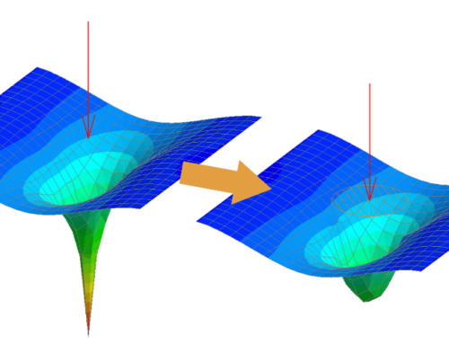
The software will apply the load in steps and try to find equilibrium in each step, redistributing the force according to the non-linear plastic material model. A somewhat similar result can be obtained by using yield line theory by hand calculation. However, to obtain this specific load distribution, you must ensure that the structure behaves in a ductile way. It is also very difficult to perform for a non-typical geometry.
The plastic shell feature in FEM-Design has a built-in ductility check by breaking the calculation when the limit strain has been reached, either in the concrete or in the reinforcement. This ensures a ductile behaviour, even at high load levels. Since it is a finite element calculation, you can calculate any arbitrary shape.
The latest patch, FEM-Design 23.002, comes with some additional results for better transparency. The new results can be found for load combinations and maximum load combinations for plastic shells and include strain and stress plots for each layer. Here, you can dive deep into the nitty-gritty of the results to better understand the behaviour of your structure.
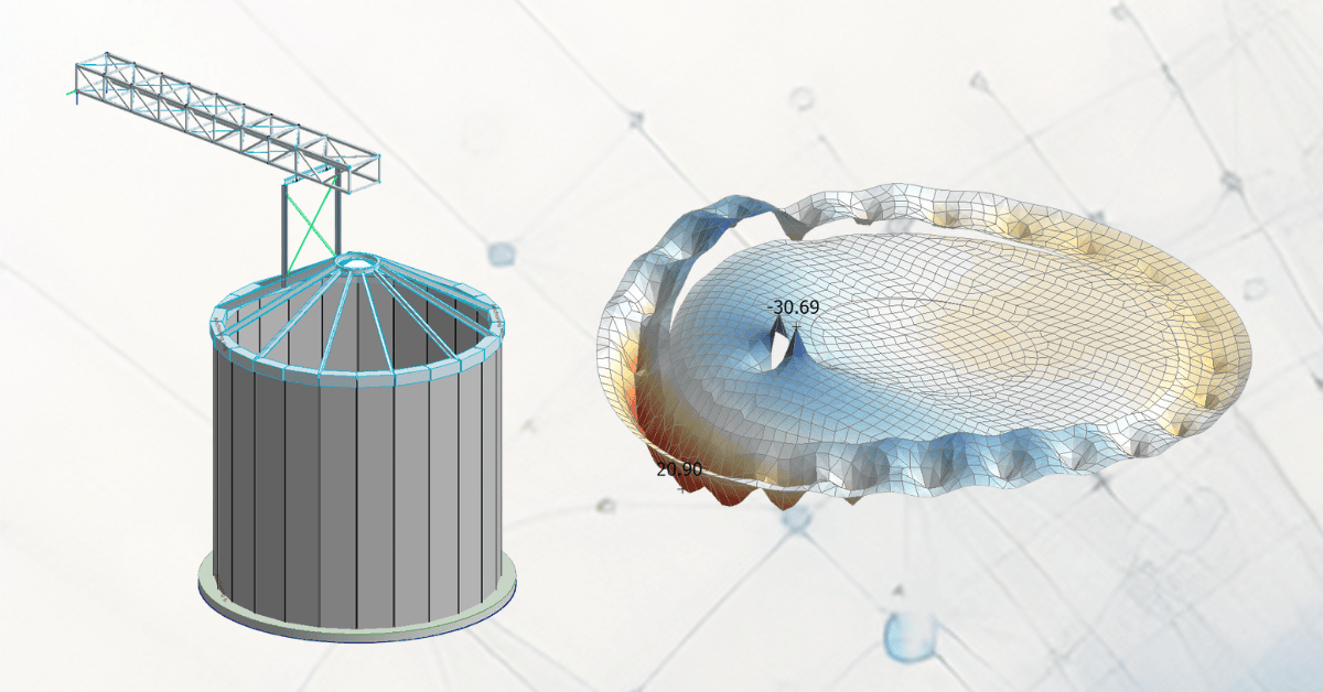
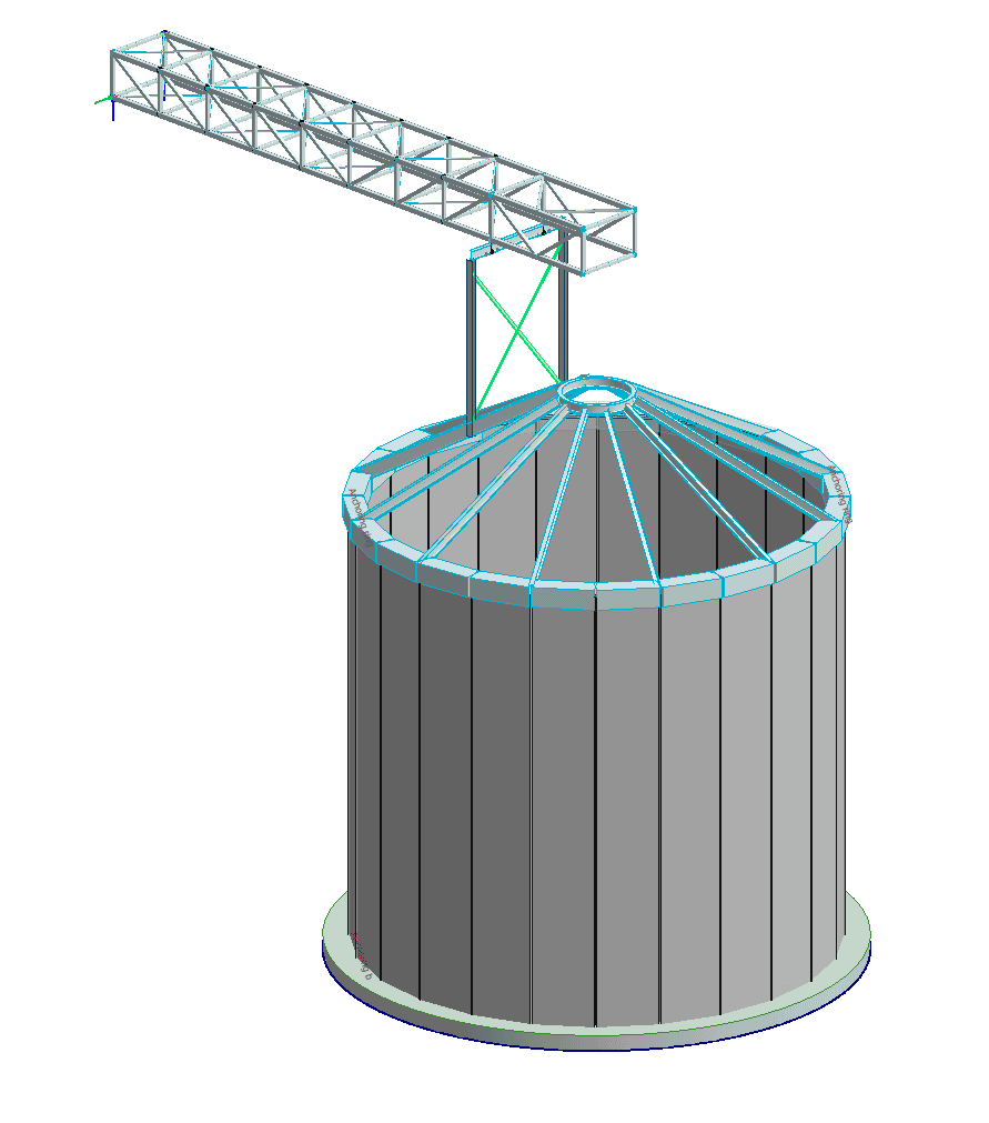
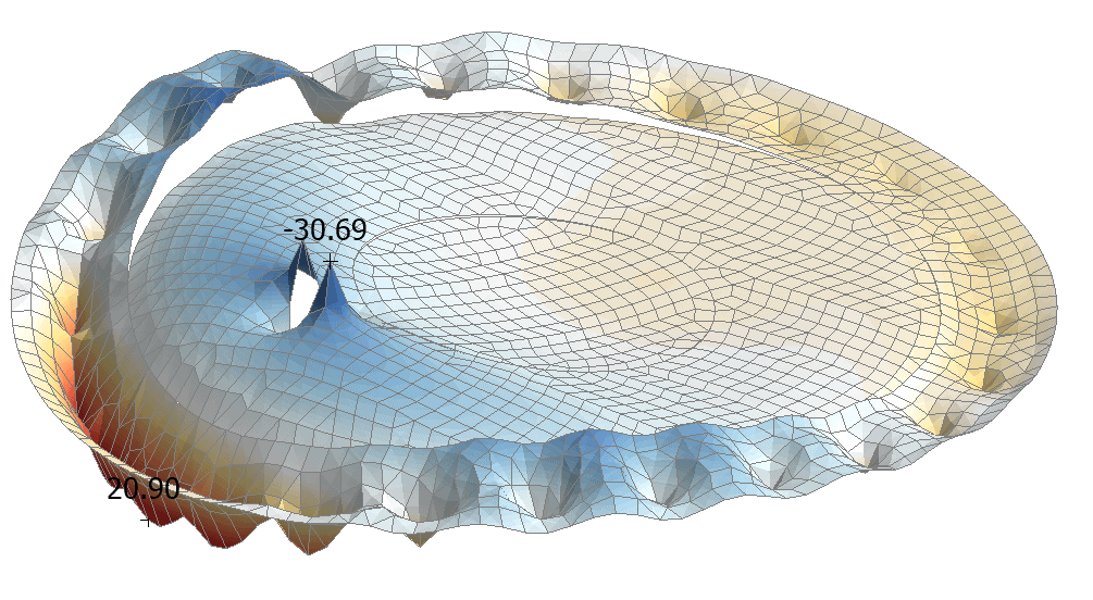
In the example structure below, the loads increased due to a change in the material stored in the tank. In the picture, you can see the moment in the base plate using the plastic shell calculation engine.
In this specific example, we obtained a maximum moment of 24.3/35.7 kNm/m for the linear model. This peak force was then distributed to adjacent areas for the non-linear plastic model to obtain a maximum force of 20.9/-30.7 kNm/m. In this specific case, a reduction of around 14%.
Take advantage of FEM-Design’s non-linear plastic shell feature for your projects
You can read more about the feature on the plastic shell page. You can also watch a recent webinar on “How to achieve material savings in concrete structures with plastic analysis and API in FEM-Design” and witness what the non-linear plastic shell feature can do for you.