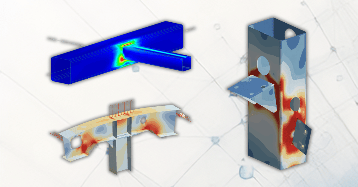
The new Plastic shell feature in FEM-Design 23 is a non-linear material model and is not only available for reinforced concrete but also for steel. This can be used to analyse different types of steel shell structures but is also a great tool for steel joint analysis and design. By modelling a realistic shell model of the joint, you can obtain stresses, stability modes, deflections, and strains in the joint. This will give you a great understanding of the realistic behaviour of your joint and help you in the design.
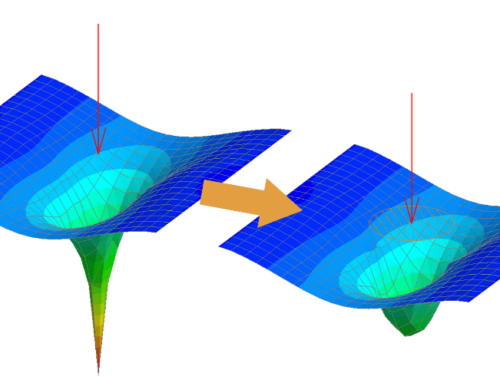
FEM-Design utilises the von Mises theory, assuming perfectly plastic material but with a fracture point of the steel when the ultimate limit strain is reached.
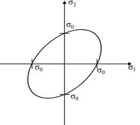
Figure 1. Von Mises flow field.
By implementing a non-linear plastic material model, you will be able to obtain plastic redistribution in the model, which in turn will reduce peak stresses and give you a more realistic stress distribution compared to a linear model. Since the limit strains of the material are implemented in the material model, you will also be able to ensure that you have enough plastic rotation capacity (or ductility) to obtain this stress distribution. If the analysis converges for 100% of the load, the analysis will be able to find an equilibrium state which satisfies the applied load with the shown stress distribution. This means that the modelled elements can withstand the loading. However, keep in mind that some additional checks may be needed, such as a bolt or weld design, to ensure a complete joint design.
To further highlight the benefit of the plastic module in this application, we have set up a simple example. Below you will find a model calculated with a linear material model. Here, you will obtain very high local stresses close to the connecting beam. This is not a realistic distribution of the force since it will exceed the stress capacity of the steel in those local areas. Instead, we want to distribute the force to a larger area.
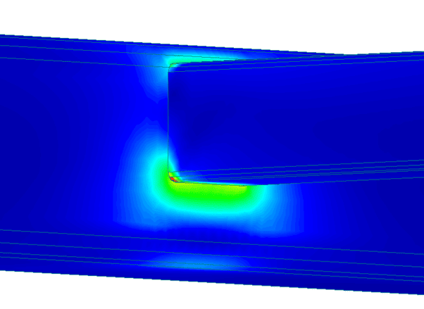
Figure 2. Linear material model – high concentration of stresses
Using the Plastic module, we are able to redistribute the stresses and we can find a much more evenly spread stress plot. Please note that the geometry and loading are the same in both cases.
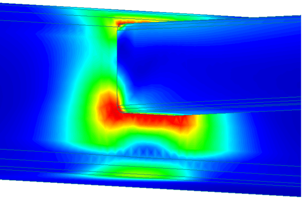
Figure 3. Non-linear material model with plastic redistribution.
By viewing the “Plastic shell condition”-result, you can visualise which parts of the shell are under plastic condition for the selected layer. In this example, we can see that we have reached the plastic limit where the top and bottom part of the beam member connects to the main beam.

Figure 4. Areas coloured in red are under plastic conditions and yellow i still under elastic behaviour.
Parametric models using Grasshopper
You can create reusable parametric models for your common steel joints by utilising the FEM-Design API for Grasshopper. We have made two example joints to get you started, one for a beam-beam connection of two KKR sections and one for a column-beam connection for H-sections. Feel free to reach out to us if you want the files.
This way, you can start creating a library of different joints that is specific to your projects and country. We would recommend starting with welded joints since they are easier to model. In addition, you can use the edge connection result for the weld design.
For bolted connection, you can model the bolts as point-point connections. Here, you are able to set a plastic limit to allow also the bolts to have a plastic redistribution when the limit force is reached. However, keep in mind that there are some limitations, such as the fact that it is not possible to apply pretension to the bolts when modelling this way. Also, you need to manually check the limit strain of the bolts to ensure ductility, and of course, the actual capacity of the bolts needs to be inserted manually.
Bonus features
Using a non-linear material model will make the deflections more realistic than a linear model. This can be utilised further to calculate the stiffness of the joint since the stiffness is just the force divided by the deflection. This can also give more realistic stiffness estimations compared to a linear model or the simplified method found in Eurocode, especially when close to the max capacity of the connection.
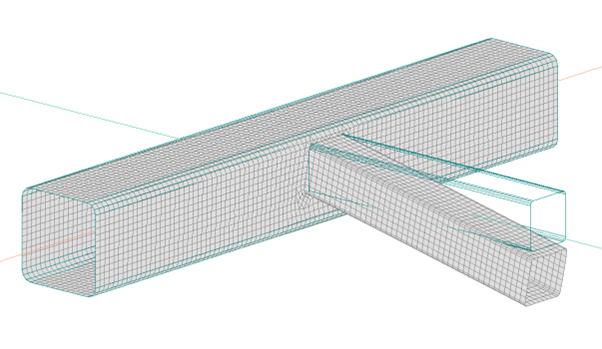
Figure 5. Detailed deflections can be obtained using the Plastic shell module.
In addition to this, you can run a stability analysis of the joint to ensure that there is no local buckling or similar. However, please keep in mind that the stability analysis is linear.

Figure 6. Stability mode 1 – a local buckling of the compressed side of the KKR.
Discover the full power of FEM-Design for steel joint analysis
Learn more about the Plastic shell module available in FEM-Design 23 on our dedicated webpage or this short video about the plastic shell for steel design.
Don’t miss our standard Steel Joint module for analytical calculation and design according to the component method in Eurocode. These easy-to-use joints will save you a lot of time and make your workflow smoother for simple steel joint designs.
We look forward to seeing the awesome steel projects you’ll make. In case you have any questions about the possibilities of steel joint analysis with FEM-Design, feel free to contact us.
