


Allplan Connection

StruSoft offers a free tool that enables smart connection between FEM-Design and Nemetschek Allplan. While the load-bearing structural objects are exchanged between the two programs via IFC, this tool allows us to insert the 3D bar and surface reinforcement objects designed with FEM-Design as intelligent, editable objects in the Allplan projects.
In this way, this dedicated tool speeds up the reinforcement editing and documentation following the analysis and design, by providing input for Allplan users with FEM-Design calculated reinforcement geometry and parameters (material qualities, bar diameters, space distributions, concrete covers, etc.), which can be put into a documentation-ready state with small modifications.
Key features
- Editable placement of reinforcement for bars, shells and foundation objects designed automatically or manually with FEM-Design in Allplan projects
- All reinforcement types that FEM-Design can design can be shared with Allplan, so the following:
- bar reinforcement
- concealed bar reinforcement
- surface reinforcement
- surface shear reinforcement
- punching reinforcement
- Ability to select which structural element’s reinforcement we want to transfer to Allplan
- Automations performed by the reinforcement standard settings of the related Allplan project during the import process:
- mesh cuttings and rebar overlapping based on the allowed starting and maximum bar lengths
- automatic hooking of stirrups
- automatic bending roller radius setup
- automatic anchorage length setup for concrete bars
- automatic rebar overhanging with cranks at column ends (where overhang is allowed)
- Automations can be overridden manually by giving custom settings values
- Ability to set crank directions and sizes for column rebars
- Automatic mark number rearrangement for the imported reinforcing meshes and bars
- Simple and straight-forward export / import procedure
- Simple data matching between FEM-Design and Allplan
- Separate Allplan drawings or layers can be assigned to different reinforcement types and positions
- The transferred 3D reinforcement can be modified in position, geometry and parameters, supplemented, labelled and listed in the same way as if it was originally created in Allplan
Download
Reinforcement export for Allplan is available as a built-in Export function of FEM-Design 3D Structure. But in order to make Allplan read the exported FEM-Design reinforcement objects, the following Allplan extension must be installed:
| FEM-Design Reinforcement for Allplan | |
| Compatibility | Allplan 2022 and later versions |
| Release date | 19 September 2024 |
| Language versions | English and Hungarian |
Workflow steps
Creation of analysis model
Since the reinforcement design and documentation is prepared and based on a physical model, it is advisable to send this physical model to the FEM-Design program (e.g. as an open-source IFC model) in order to create the analytical model that simplifies it for calculations and designs.
Of course, modelling can also start in FEM-Design, but the more common case is when a physical model comes from an architectural program or from a structural detailing program (such as Allplan) itself.
The following figure is an example of a physical model of a reinforced concrete structure created in Allplan.

From the IFC file saved from the model, FEM-Design can build the analysis model required for load -bearing and transfer, the finite element calculations and the detailed reinforcement design.

Design of applied reinforcement

The Reinforcement design module of FEM-Design provides the opportunity for detailed concrete and reinforcement design of the entire model or only for selected bar and shell objects.

FEM-Design is able to display, list and document the reinforcement design results in a professional manner with full details of the applied calculations. The following figure shows a documentation part of a designed reinforced concrete beam.

Reinforcement export from FEM-Design
The designed reinforcement can be exported very simply to Allplan. Just select the concrete objects, whose reinforcement wanted to be shared with Allplan (so the host objects), with the dedicated Export to Allplan command (File menu).

Analysis object selection can be done in any mode (Structure, Loads, etc.) and view, and their reinforcement does not need to be displayed. Selection can be done for all visible reinforced concrete objects, or even just one (e.g. a plate) or certain functional types (e.g. foundation). Of course, in the case of a large or complex model, the selection can also be helped by filtering the model view to only the elements to be selected until the time of export.


Comments
- The following import settings include global ones (e.g. manually specified Geometry settings values), so it is advisable to consider which reinforcement objects we want to handle together and which separately at the import. More than one file can be exported, as any number of subsequent imports can be performed.
- All designed reinforcements of the selected objects are exported in .fd2allplan file format dedicated to the connection.
- The base net bars can be filtered out at the Allplan import.
Import reinforcement into Allplan
The import is performed by the FEM-Design RC Import add-on tool installed on Allplan (see Download). After installation, the add-on functions can be achieved via the path shown in the picture: Library > Default > PythonParts.

The import is performed in two simple steps:
- Select the .fd2allplan file saved with FEM-Design by specifying the path to its storage location.
- Execute the import by specifying the import settings to automate and perform additional operations on the loaded reinforcement objects:

Marks

- Auto rearrange combine marks of bar or area reinforcement having the same shape and cross section and placed on the same drawing file.
- Start number for bar and/or area reinforcement, which is recommended to be different from the existing reinforcement identifiers for the sake of joint listing and management.
Geometry settings

- Bending roller radius and Hook length for stirrups
- Parameters required for cutting and placing area reinforcement (meshes) including Overlap length, Starting length and the Max bar length.
- The “Auto” value available for each parameter means that the Add-On automatically sets their value based on the Reinforcement Standard applied in the current Allplan project (e.g. the hook length values are the prescribed multiple of the imported bar diameter).

- Area placement method for setting the way of the internal management of the imported area reinforcement:
- In polygon means that placed bars are managed separately, so a full schema of each individual bar can be created later.
- Per meter means that only the placing lengths are managed, so the creation of a schema merely results in a value showing the number of meters.
Note: If area regions with identical external contours have rebars oriented in the same direction and planar position, and with the same spacing, then the distribution of bars within each region will automatically adjust relative to one another, ensuring equal spacing between resulting bars (halving, thirding, … the bar distances). Thus, in this specific scenario, the overlapping and obscuring of bars are avoided. In cases where regions have different contours, it is recommended to run the Collision check function of Allplan if we cannot discover bars obscured by other bars.

- The methods for importing or creating anchorages for rebars in beams and columns, including the possibility of cranking for columns:

-
- Anchorage length for bars (“AL” in the next image)
- Auto value sets the anchorage length for each rebar automatically based on the Reinforcement Standard applied in the current Allplan project.
- By FEM-Design value applies the anchorage lengths set by and exported from FEM-Design.
- Custom allows us to define a global anchorage length for all rebar overhangs related to concrete bar objects.
- Rebar overhang at beam ends
- No (default) ignores anchorages independently FEM-Design exported overhangs or not.
- Yes creates anchorages with the length specified by the value of the option Anchorage length for bars.
- Yes, with cutback imports anchorage sections that are inside the beams and are cut back by a given Cutback distance from beam ends.
- Rebar overhang at column ends
- Yes, with cranks (default) anchorages with the length specified by the value of the option Anchorage length for bars, and automatically cranks the overhangs (e.g. allowed for column tops) with the crank settings (see later).
- Yes creates anchorages with the length specified by the value of the option Anchorage length for bars.
- No ignores anchorages independently FEM-Design exported overhangs or not.
- Crank settings for rebars at column ends:
- Crank direction can be specified as centerward or relative to the axial directions of the affected concrete columns.
- Crank extend (“CE” in the image), which is equal with the diameter of the rebar in case “?” is set to 0.
- Crank start (“CS” in the image) defines the distance from the top plane of the slab located between columns, or, if the slab does not exist, the distance from the end of the related column.
- Crank length ratio (“CLR” in the image)
- Anchorage length for bars (“AL” in the next image)

- The Punching studrail installation method specifies the position of the studs and rails for all Studrail-type (general or Peikko PSB) punching shear reinforcement objects in the imported file.

Steel grade mapping
Material matching/pairing between the rebar materials exported from FEM-Design and those to be used in the project.

Layout and separation
- Import base nets option enables basic reinforcement to be filtered out of the objects to be imported, so its off status imports only the secondary/additional area reinforcement.

- Apply Drawing file(s)
- Different per RC type lets placing the exported reinforcement objects separately by type (bar/area/unique area/shear area/punching), by position (bottom/middle/top) and/or by direction (x’/y’) on Drawing files with different or same IDs.
Note: Due to the limitations of the Allplan API, only the number of a Drawing file can be entered. The name of each Drawing file can be assigned before or after import.

-
- One for all places all exported reinforcement objects on one Drawing file with a given ID, and optionally on Allplan’s default layer structure based on their types, positions and directions (e.g. Area reinforcement, bottom x’ goes to layer numbered “3842”).

Reinforcement editing (briefly)
After importing with the Execute button, all bar and surface reinforcements are created as parametric, editable, schedulable and documentable so-called “Bar Shape” objects in the current Allplan project. Reinforcements can be displayed in the current windows by activating the Drawing files or Layers assigned to them.
The parameters of a reinforcement – for example stirrups – suggested by FEM-Design calculations (e.g. spacing, bar diameter, length, etc.) and extended by import settings (e.g. with hooks) can of course be modified at any time before or during documentation.

If, for example, the position of a beam reinforcement differs due to discrepancies between the analytical and physical model, it can be easily modified with the editing functions of Allplan.

The surface reinforcement is generated as Span-type Area Reinforcement during the import, so editing operations typical for those object types can be applied (e.g. the placement modification).

The display of imported reinforcement objects (e.g. the Placement Display Mode) can also be set according to the usual methods in Allplan (as if the reinforcement had been created in Allplan from the beginning).

Documentation, labelling and reports (such as bar schedule tables) can all be carried out in detail for both bar and surface reinforcement objects.


Why wait? Download an automated 2 x week free trial of FEM-Design and get started today!
FEM-Design Wiki
Full details on the Allplan connection can be found on the FEM-Design Wiki by clicking here.
Calculations performed according to:
FEM-Design performs all structural calculations to Eurocode standards, with support for 15 National Annexes across Europe. Whether you’re designing in Denmark, Netherlands, Poland or the UK, FEM-Design ensures full compliance with your local requirements.
 Eurocode
- Belgian Annex
- British Annex
- Danish Annex
- Dutch Annex
- Estonian Annex
- Finnish Annex
- German Annex
- Hungarian Annex
- Latvian Annex
- Norwegian Annex
- Polish Annex
- Romanian Annex
- Spanish Annex
- Swedish Annex
Languages supported:
- English
- Finnish
- French
- Dutch
- Hungarian
- Polish
2nd Generation Eurocode under development

FEM-Design Blog
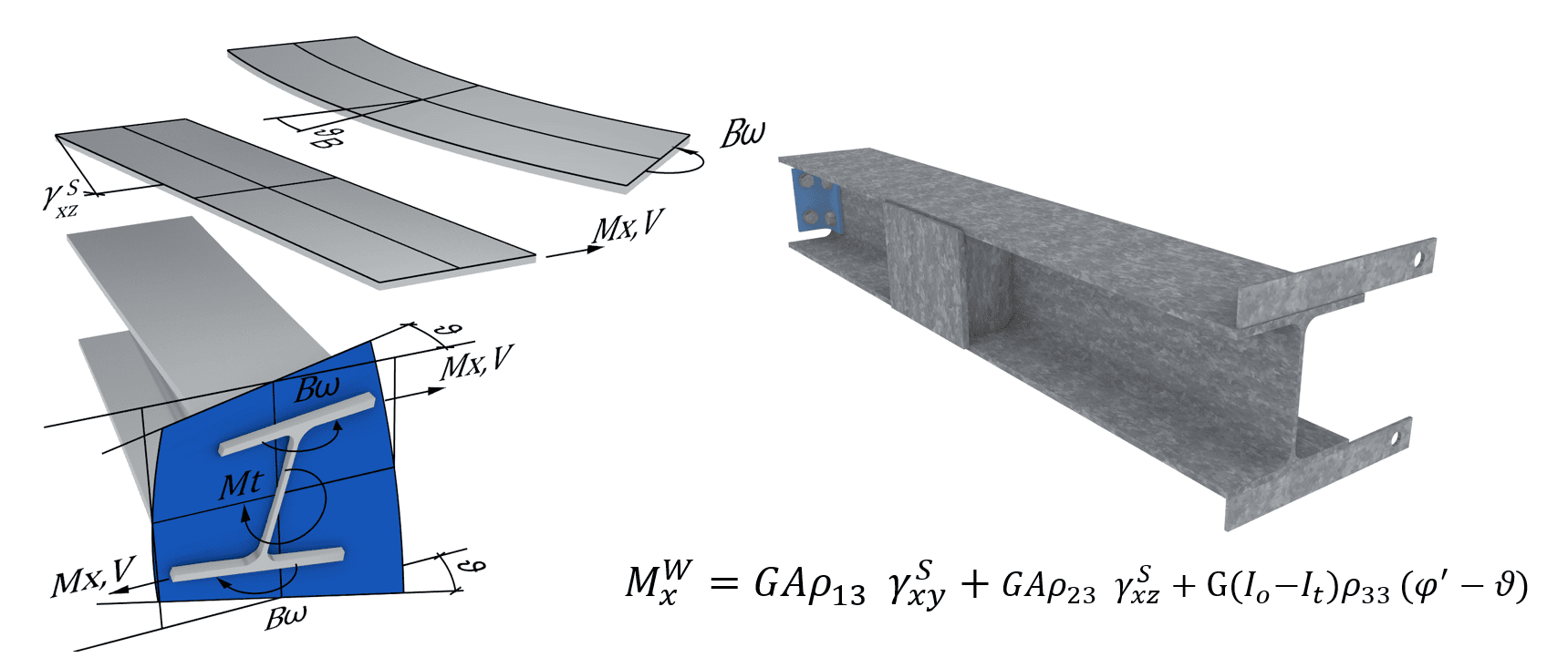
7DOF Beam – Common Questions
Answers to common questions about 7DOF torsional warping. What is 7DOF or Torsional Warping? Torsional warping is a phenomenon that happens to all real [...]
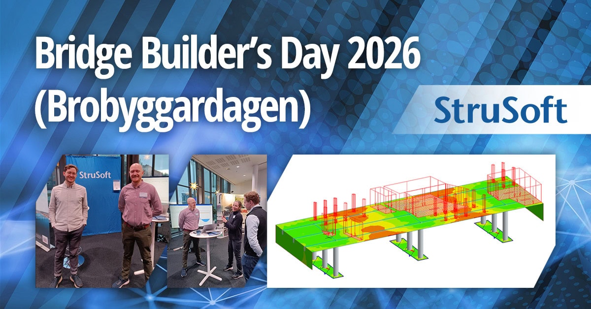
Brobyggardagen 2026 – Bringing the Bridge Community Together
Bridge Builder's Day 2026 (Brobyggardagen) once again brought together the bridge engineering community for a day of knowledge‑sharing, innovation, and practical insight. Known for [...]
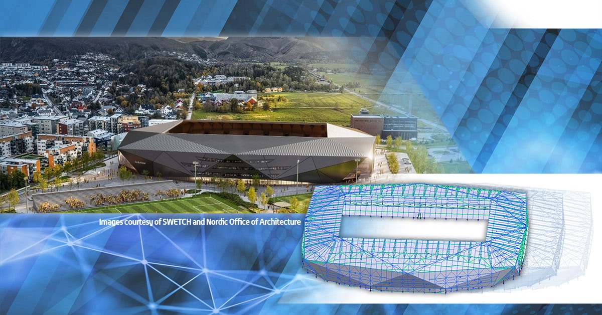
SWETCH Used FEM-Design for the Steel Frame Structure of the Arctic Arena in Bodø
The structural design company SWETCH is currently developing a steel frame structure for the home stadium of the Bodø/Glimt football team – The Arctic [...]

Bio: Panos has worked for over 5 years as a structural engineer before joining StruSoft in 2025, using WIN-Statik and FEM-Design in his daily practise. Panos ...show more understands the practical needs of todays customers and will help them solve their daily problems with any StruSoft software. Feel free to contact Panos if you need any technical assistance or would like a training or a demo of our structural software. show less

Bio: Mikkel is responsible for the sales of all our structural software in Denmark. With a background in civil engineering and hands-on experience using FEM-Design for ...show more large-scale projects, he understands the challenges engineers face. Mikkel’s goal is to help Danish companies find the right structural software solutions to optimize their projects and meet their specific needs. show less

Bio: Joni has helped and trained hundreds of engineers in structural analysis in Finland. He works in both civil and mechanical engineering fields with structural analysis. ...show more Joni has over 15 year of experience in structural design of many types and sizes of steel, concrete and timber structures. Joni is the Product Owner of our JIGI software and Country Manager for Finland. Please free to contact Joni if you need any help to solve your structural analysis problems. show less

Bio: Marek Krawczyk is the Country Manager for Poland at StruSoft. As a structural engineer, he has more than ten years of international experience, working on ...show more various projects in Europe, the UK, the USA and Asia. He joined StruSoft in 2022 to strengthen our presence in Poland and support the StruSoft software Users in the local market. show less

Bio: Ciprian Tibea is the Sales Manager for Baltics & Romania and has been with StruSoft since 2018. Ciprian has a PhD in Civil Engineering (Ultra ...show more High Performance Concrete Subjected to Shear Action) and a Masters Degree in Entrepreneurship and Business Administration. Prior to StruSoft, Ciprian was working as a research engineer for Consolis for 6 years and for 1 year with a local company in Romania working on structural design projects with advanced Finite Element Software (Diana and Atena). Ciprian is your main Structural Sales contact for markets outside Europe, the Baltics and Romania. Please feel free to get in touch. show less

Bio: Mohsen Ghaemi is the Hungarian Manager for StruSoft in our Structural Business Unit. He has a PhD in Structural Civil Engineering (Topology optimisation). Mohsen has ...show more been with StruSoft since 2002 and has more than 20 years of experience with the FEM-Design software and its development, as well as in customer relationships and sales. Please feel free to get in touch with Mohsen directly. show less

Bio: Victor is Customer Success Engineer at Strusoft situated at our Gothenburg office where he works in close contact with our customers to help them use ...show more our software in the best way possible. He has a background as a structural engineer with many years of hands-on experience of using FEM-Design and WIN-Statik in his day-to-day work for large and small projects alike. Please feel free to contact Victor if you need guidance in FEM-Design, are interested in a demonstration or have any general questions. show less

Bio: Jan Wróbel has over 6 years prior experience before joining StruSoft working as a structural engineer, using FEM-Design and WIN-Statik in his daily practice. His ...show more international project work has equipped him with broad technical knowledge and understanding of various design standards and client needs. He is now focusing on technical support for Polish customers. Feel free to contact Jan for any assistance with StruSoft's structural software or any other structural engineering questions! show less

Bio: Markus Mitikka is a customer coach for StruSoft in Finland. He has previous experience of FEM calculations and structural designs working for engineering office. He ...show more was a big fan of StruSoft software before joining StruSoft in beginning of 2022. Markus can help you to become more efficient with all our structural software. Please feel free to get in touch. show less

Bio: Casper Hougaard is Owner of Market & User Value for FEM-Design, and Product Owner for PREFAB. He joined StruSoft in 2022 and has a background ...show more in civil engineering with lots of practical experience using FEM-Design. Casper helped hundreds of customer as a Customer Success Engineer in Denmark before transitioning to the development department. show less

Bio: Fredrik Lagerström MSc has 8 years prior experience before joining StruSoft working as a civil engineer using FEM-Design, WIN-Statik & PRE-Stress in his daily practice. ...show more In 2011 Fredrik joined StruSoft as a Technical Sales and Education Manager. Fredrik works closely with both Sales and Development to get feedback directly from our Swedish Customers to in turn help our Developers to implement the requested new features in an accurate way. Please feel free to get in touch with Fredrik if you require any technical help or support with our structural software. show less

Bio: Shahram Omary is an account manager at Matrix Software, the Dutch affiliate of StruSoft, specializing in structural software solutions for the Dutch construction sector. With ...show more a strong technical foundation in civil engineering and a master’s degree in Construction Management and Engineering from TU Delft, Shahram combines academic insight with practical industry experience. His background spans roles in design, preparation/planning, and engineering consultancy firms. Shahram is passionate about digitalization and innovation in structural design, striving to deliver tailored software solutions that align with clients' technical and business goals. Currently, he is responsible for market strategies based on market analyses in the Dutch market, with potential expansion into the UK market. In parallel, he also contributes to the marketing aspects related to the current promotion of the software packages, including FEM-Design, in collaboration with the marketing team. show less


Bio: Botond Előd Nagy is a Structural Civil Engineer focusing on professional and academic education, with a strong emphasis on innovative, technology-driven solutions.

Bio: Tobias has 4 years of experience as a structural engineer working a lot with prefabricated concrete elements from a consulting firm in Denmark. His mission ...show more at StruSoft is clear: to help our customers solve real-world challenges using our structural software. show less

Bio: Suhas is the Managing Director of StruEngineers India, a Design & Detailing Service company 100% owned by StruSoft. Suhas has a BSc in Civil Engineering ...show more and has been providing design support services to the Precast Industry, worldwide, over the last 20 years. Suhas was one of the original founders of StruEngineers which was established 10 years ago and previously worked for Neilsoft in Pune. StruEngineers provides local support in India for all StruSoft software and Suhas is a specialist with IMPACT AutoCAD. If you are based in India and looking for more information or support please feel free to get in touch directly with Suhas. show less

Bio: Anders Nilsen joined StruSoft in 2019 and starting of as a Sales Manager in Denmark. In 2024 Anders took on additional responsibilities as Head of ...show more Sales in Denmark, The Baltics, Hungary, Romania, Poland, UK & Ireland in the structural business unit of StruSoft. Anders has a background as a civil engineer with lots of practical experience in all our structural software. show less

Bio: Ákos joined StruSoft in 2000, working in sales and technical support for the Hungarian market until 2008. Over the following years, he specialized in BIM ...show more technologies and multidisciplinary structural design workflows. Since 2020, Ákos has been part of the FEM-Design development and marketing team at StruSoft, where he is responsible for BIM connectivity and interoperability solutions. His work includes the specification, coordination and promotion of open-standard (IFC, SAF) and API-based workflows with industry-leading platforms such as Revit, Archicad, Allplan, IDEA StatiCa and Tekla. show less