FEM-Design has for many years been known for its great concrete design, but the last two versions came with even more features and improved automatic design algorithms. Get going with the new powerful features and save both time and materials!
Documentation – Step-by-step report with all formulas and checks, including Eurocode references
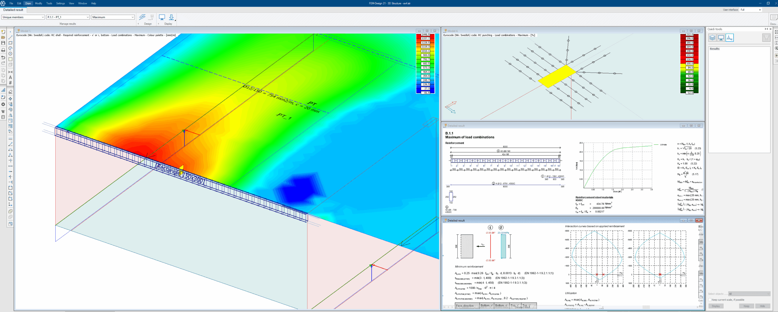
A big goal for the FEM-Design development is to have transparent and clear presentations of all design checks carried out in the software. From two years ago, you can obtain step-by-step reports for all checks implemented in the software, regardless of situation, material or other. Yes, even for shells! The presentation shows all relevant formulas with Eurocode references. This will not only make it much easier to understand and manually check the design but also be a great addition to the documentation for the project.
Tip: Select the “Utilization” result and choose the magnifying glass. Right-click on an object to see all checks carried out for the specific result.
Bar design – Powerful auto design and easy manual input of reinforcement
Did you know that it is now possible to set symmetry conditions for the automatic bar design? You can also idealize the loading situation by ignoring torsion forces in bars for the design. This means that you can perform design of individual members in the global model in more cases which saves both time and energy.
If you wish to check an existing bar, you can easily add the reinforcement by using the parametric reinforcement layout feature and make manual adjustments to your specific situation. In the manual design window, you can also view the interaction volume for My, Mz and N!
Tip: Go to the display settings and show the applied reinforcement. Now you can view the reinforcement in the 3D view to get a better understanding of the layout.
Shell design – Improved auto design algorithm, crack width calculation and non-linear material
FEM-Design 21 comes with an improved algorithm for automatic shell design. This algorithm will generate a layout with about 10-20% less reinforcement than previous versions. This new algorithm is a great starting point for the reinforcement layout and will save you time and materials in your design.
Visualize the cracks calculated according to Eurocode in the 3D view and design the reinforcement with regard to the crack width. Take your analysis to the next level and perform a non-linear analysis considering the decline in stiffness caused by the cracking. This non-linear calculation will typically result in a more beneficial load distribution with reduced reinforcement since areas with high concentrated loads will crack and be unloaded.
Tip: You can select to automatically design the shells with a fixed diameter or spacing. Here you can also select which algorithm to use (the new algorithm is called “Minimal area of rectangles”).
Punching and shear – Design your shell shear and punching reinforcement
Punching design is available for both columns and wall ends in FEM-Design. You can define the area manually or let the software detect possible punching regions automatically. Run the check only with longitudinal bars or add extra punching reinforcement in the area.
In FEM-Design 22, it will also be possible to design and add shear reinforcement in different areas. Using the built-in feature, you can add shear reinforcement to your plate or wall to obtain extra shear capacity besides the capacity obtained from the longitudinal bars.
Tip: Did you know you can change the automatically generated punching area? This can be used in cases where you have a top plate or a column capital. Use the “Modify region” tool or another CAD-tool to change the region.
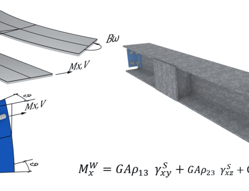
Concealed bar – Design part of your shell as a bar!
With the feature called Concealed bar, you can design part of the shell as a bar. The software will integrate the forces over an area to obtain the corresponding forces in a line in the shell. This line is then designed as a bar object with stirrups and longitudinal bars at the top and bottom. This is a great tool for designing concrete areas above openings or edge beams in plates.
Tip: Did you know that concealed bars can have any direction? You can just as easily use it to design part of a wall as a column!
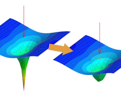
Great peak smoothing settings
Peak smoothing is a must when dealing with concrete design based on forces from a finite element analysis. This is because of possible singularities in the analysis result but also comes from the common practice of distributing the forces with regard to cracking, support width or similar. FEM-Design has some great features for peak smoothing where you can automatically generate the areas or manually define them. The area is mesh-independent which helps to keep a structured mesh even though many peak smoothing regions are used. You can select which internal forces you want to apply peak smoothing to and the method of how to distribute the mean value. Either a constant value over the area or distribution as a parable.
Tip: It is often a good idea to apply peak smoothing for the moment internal force but not on the shear force. Since the shear force is the derivative of the moment, the maximum moment (where you usually want to apply peak smoothing) coincides with the position where the shear force changes sign. Taking an average value over an area with two different signs in the shear force often results in a cancelling-out effect.
Fire design – Advanced fire design for shells and bars
The fire design in FEM-Design Concrete 3D is based on a finite element analysis of the heat flux in the section. This means that all kinds of sections can be designed for fire. Because of this, it is also possible to reduce the material properties of every individual reinforcement bar taking into consideration the actual temperature in that position. It is also possible to design plates and walls for fire in FEM-Design 22.
Tip: The available design methods for the fire design are the zone method and 500° isotherm. The zone method divides the section into different zones, and each zone has reduced material properties concerning the temperature in that position. The 500° isotherm reduces the section and ignores concrete where the temperature exceeds 500°C.
Did we mention that all this, and more, is included in one module – the FEM-Design Concrete 3D module?