Introduction into plastic shell modelling with FEM-Design
FEM-Design 23 comes with a new module for non-linear calculations. It combines the existing features for plastic modelling of supports and connections with a new and improved way to model steel and reinforced concrete. This model will allow you to capture the behaviour of concrete from first cracking to failure in a more detailed way than previously.
Why is plastic analysis needed?
The main benefits of the new analysis method are:
- Closer to truth deformations
- More accurate load distribution
- More accurate internal forces
- Savings in material usage
When is plastic shell modelling useful?
The plastic module can be beneficial in several different scenarios. It is especially useful when loads can redistribute and when the stiffness difference between uncracked and cracked concrete is important. A couple of examples are described below.
An alternative to the strut-and-tie method
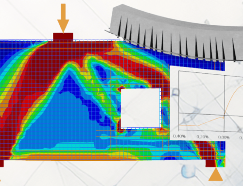
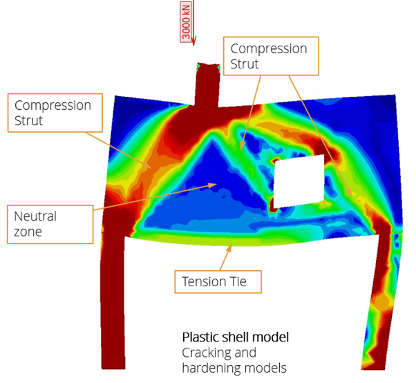
When designing a high beam like a transfer wall, a common method is to use the strut-and tie method to find load paths and design reinforcement. The plastic model can be used as an alternative or a complement to this method. It will help you see the main load paths, but in contrast to the strut-and-tie method it can utilize the concrete and reinforcement outside the main struts and ties. Thanks to this, you can often save material using the plastic analysis method.
The image shows the plastic shell model in action. You can see the load carrying behaviour of the wall clearly.
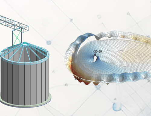
Complex multi span plates
Another application is slightly more complex multi span plates. There are often some zones with higher internal forces, and the reinforcement in these zones would have to be increased using the regular elastic analysis method. Using plastic analysis, we can see that the forces are evened out when the concrete starts cracking and the loads redistribute to stiffer parts of the plate. We also get a more realistic distribution between support and field moment forces.
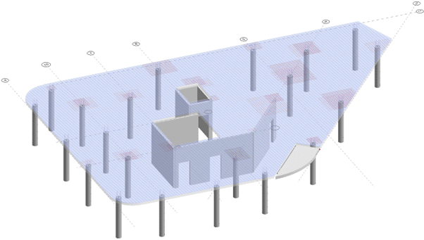
A typical office building floor slab.
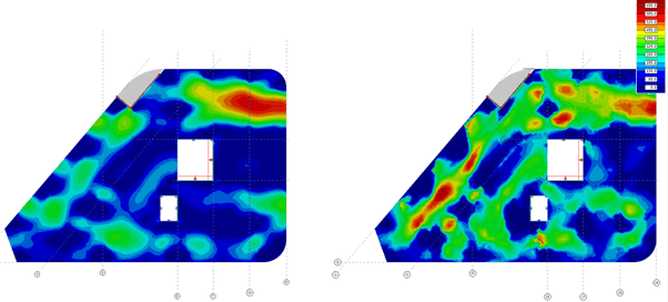
The required bottom reinforcement, using the elastic model on the left, and the plastic model on the right.
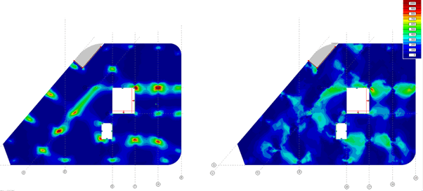
The required top reinforcement, using the elastic model on the left, and the plastic model on the right.
How plastic shell modelling works
Some information on what is happening under the hood follows below. For those who want to dive deep into the theory, please look at the technical documentation. For a shorter summary, continue reading.
Incremental loading
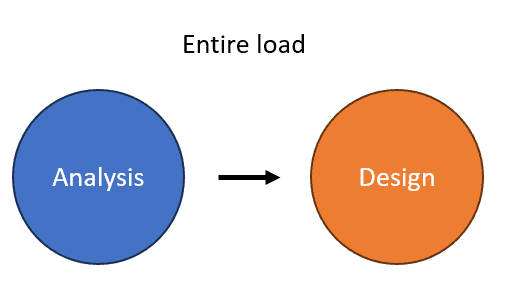
In most FE programs, including FEM-Design, the analysis and design are two separate things. The model is built, then the analysis is run. The resulting stresses and displacements are then post-processed in the design, where it is decided whether your structure can hold up to the applied loads or not. The analysis only considers the stiffness of elements, not the capacity. Therefore, you can load the structure with any load and the analysis will still be able to run and converge.
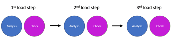
In the new module, the analysis and design checks are integrated into each other, so that they happen simultaneously. It is an iterative process, where a percentage of the load is added for each iteration, the analysis is run, and the stresses are checked for plastic limit and ultimate limit (failure). When parts of the structure start to plasticize, loads may be distributed to other parts of the structure.
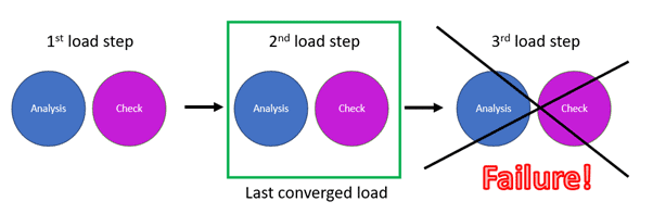
In case some part of the structure reaches failure before the whole load is added, the iteration will be stopped, and you will get information on how much load could be added before failure.
This means that you should not use the concrete design or steel design modules with regard to cross section bending capacity and combined tension-compression capacity checks since it is integrated in the analysis phase.
Layered shell model
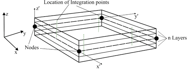
To be able to model the correct plastic behaviour of steel and reinforced concrete, a special type of shell element has been added to FEM-Design. It divides the plate into several layers (number of layers can be chosen by the user) as compared to the regular shell which has just one layer. This makes it possible to capture the through-thickness variations and results can be displayed for each layer. The theory behind this is described in detail in the technical documentation.
Material model
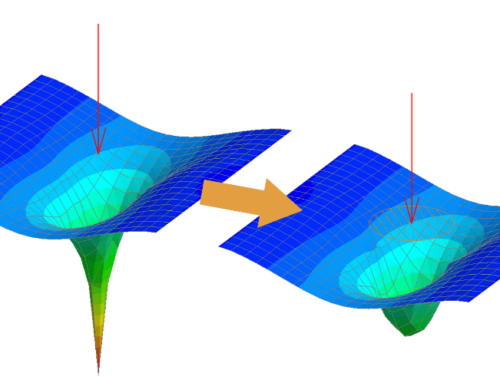
The material model for concrete that is used in the new module is a lot more detailed than the previously existing one. In FEM-Design an elastic material model is default for both steel and concrete. To be able to calculate deformations according to the Eurocode, there is also a simplified “cracked section” material model for concrete.
In situations where the stresses are relatively low, you can see that the different material models give similar results. However, when compressive stresses are large, and when tensile stresses are higher than the concrete tensile strength, the material models differ a lot.
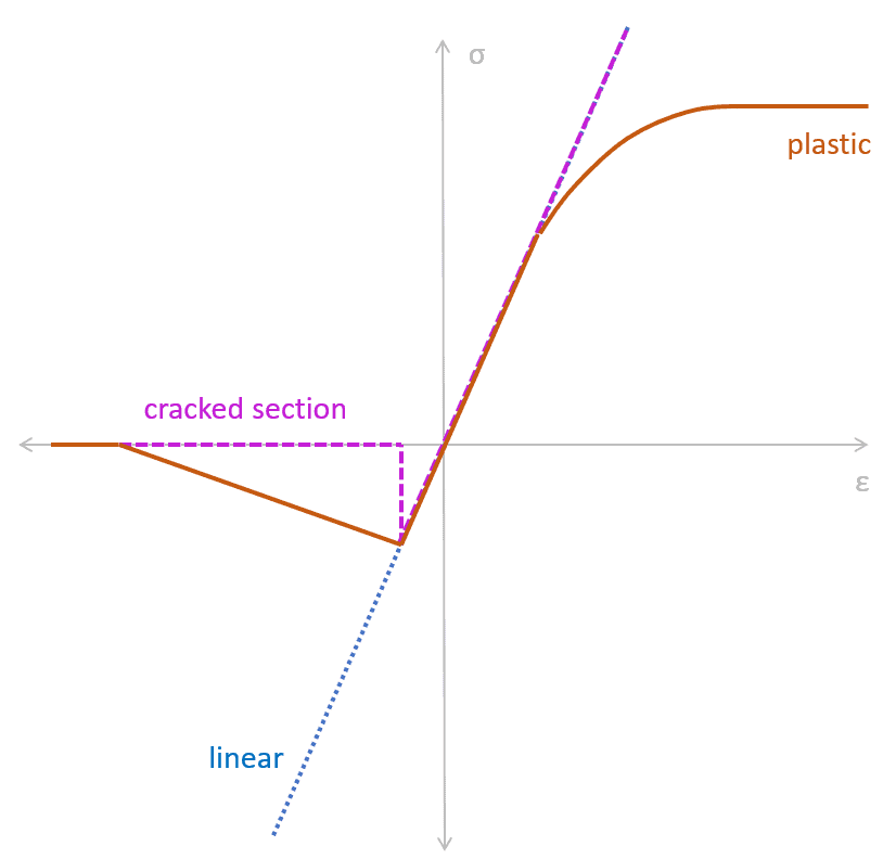
Comparison between the different concrete material models in FEM-Design.
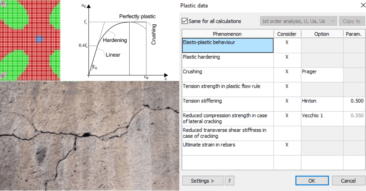
The plastic material model also comes with different settings, so that the user can customize how they would like to model the materials. This can be useful to create a more conservative model or a model with better calculation speed.
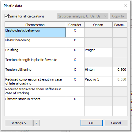
The different settings available for the material model.
| Setting | Explanation |
|---|---|
| Elasto-plastic behaviour | Turns on elasto-plastic behaviour of the element. |
| Plastic hardening | Affects the stress-strain constitutive law, accurately depicting concrete’s hardening phase. |
| Crushing | Controls the concrete damage model, by comparing an equivalent strain found from in-plane ε1 and ε2, to the uniaxial compression limit εcu2. |
| Tension strength in plastic flow rule | Disabling it makes concrete in tension perfectly plastic, removing tensile strength but possibly reducing deformation accuracy. |
| Tension stiffening | When considered, it improves deformation results by accounting for the tensile load carried by cracked concrete due to the bond between reinforcement and concrete. |
| Reduced compression strength in case of lateral cracking | Modifies compressive strength in response to tensile strains by dynamically adjusting the effectiveness factor during analysis. |
| Reduced transverse shear in case of lateral cracking | Cracking reduces transverse shear stiffness, adjusted by reducing shear modulus proportionally to the strain. |
| Ultimate strain in rebars | Controls the steel strain limit εu; exceeding it fully damages the material point, impacting load capacity. |
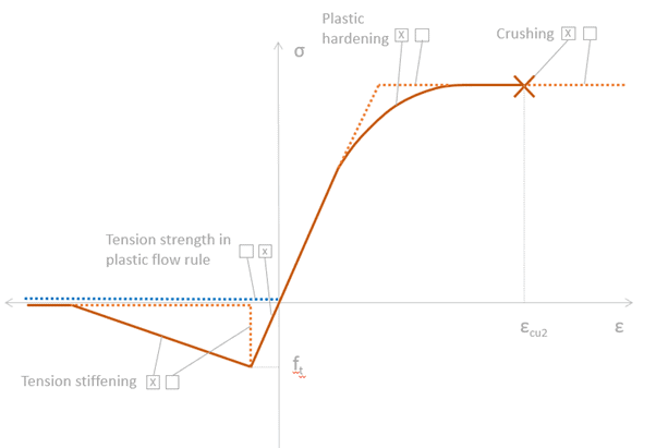
Figure illustrates how the different settings for the plastic material influence the material model.
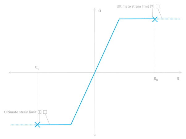
The material model for steel and reinforcement steel.
Are you eager to use plastic shell modelling in FEM-Design 23?
If you want to learn more and see the new plastic module in action, join us for a free technical webinar hosted by our colleagues Isak Bjorhag and Johanna Riad on February 20th. The webinar is done in collaboration with the Institution of Structural Engineers UK (IstructE). You can read more details and register here. You can also check the dedicated blog post for this webinar on IstructE’s website at this link.
Do you already have a few thoughts in mind for how you’re going to use plastic shell modelling in your structural engineering projects? Feel free to contact us if you have any question. We would be happy to help you use the new plastic module to the fullest extent possible.