Considerable development has been done to improve the automatic design and reduce reinforcement in concrete shells with FEM-Design v21.
A new algorithm has been implemented, which can save you by up to 20% reinforcement in shells due to a more optimised layout. In this article, we will look at an example and evaluate the difference between FEM-Design v20 and v21.
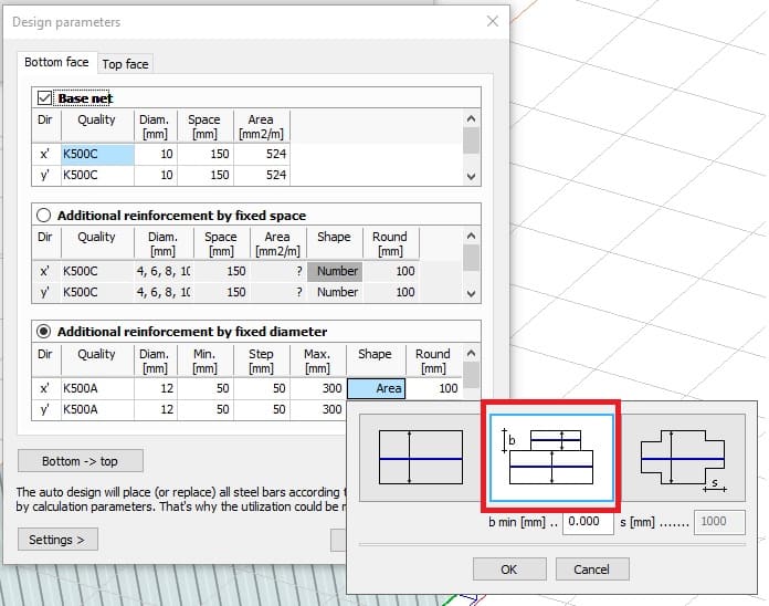
We have both improved the existing methods and introduced a new option for reinforcement layout. This setting can be found in the auto-design settings under “Shape”. The new layout option is called “Minimal area of rectangles”, and it will try to divide the reinforcement in a structured yet optimal way.
The example below is a multi-storey building made with in-situ (RC) concrete. It consists of concrete walls and slabs with concrete columns.
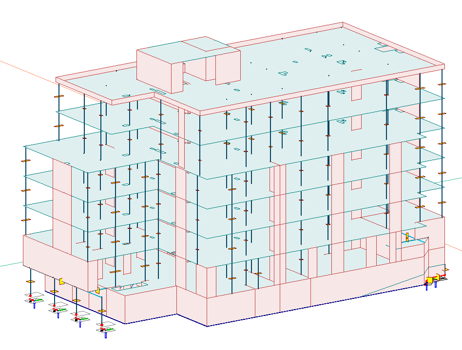
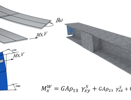
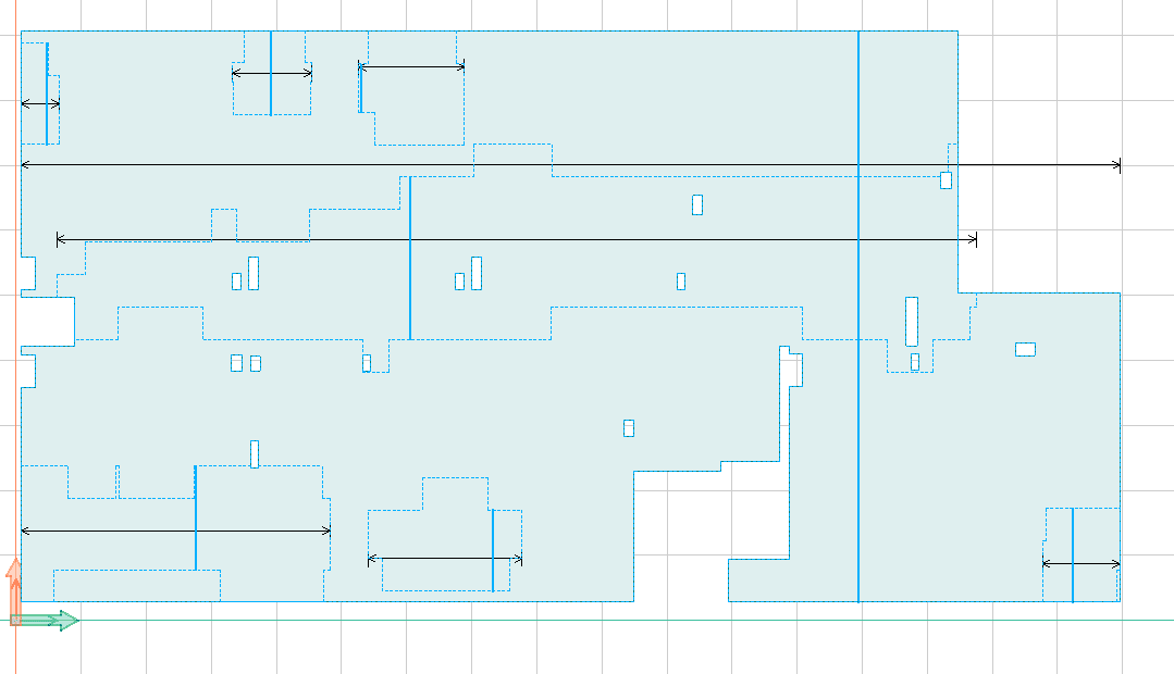
We will focus on the top-level slab and make a comparison between FEM-Design v20 and v21. Let’s start by running the auto-design in FEM-Design v20. In this slab, the shape method that gave the least amount of reinforcement was “Stepped”, and it generated a layout found in the picture below:
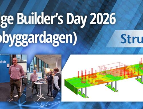
If we instead use the new “Minimal area of rectangles” in FEM-Design v21, the auto-design layout looks a bit different:
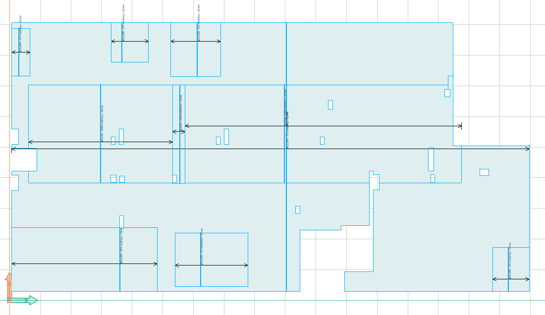
The new method gives a more structured layout but still will a lower total weight of the reinforcement. If we make a quantity estimation and compare the reinforcement applied, we can find a 22% reduction to reduce reinforcement in concrete shells using the new algorithm in FEM-Design v21.
| Reinforcement [tons] | |
| FD20 | 128,89 |
| FD21 | 101,14 |
| Difference | 22% |
We continue to develop more advanced optimisation tools to help you save both money and the environment. If you would like to find out more about all the new features in FEM-Design v21, please visit the FEM-Design Wiki by clicking here.