“Why do the results differ for Timber Deflections from hand calculations to the FEM-Design software?”
This is a recurring question to our Support Team that we hope to provide some insights with this post. Usually, the most common factor is that Users have different approaches when combining loads and the deformation factor kdef.
Let’s look at how this works in FEM-Design. The elastic modulus used for the various analysis types in the program follow the table below.
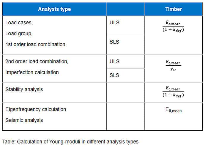
Here it is clear which analysis types consider the deformation factor kdef. Since FEM-Design version 19, it has been possible to set different kdef values for different load combination types.
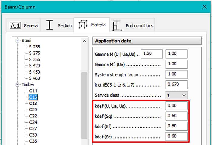
So, if you do not want a time dependency for a load combination type, you can set kdef for this to zero. See screenshot below.
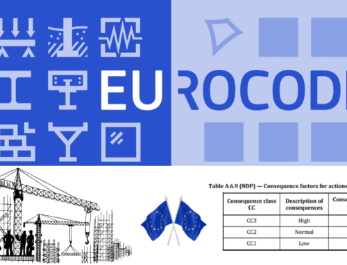
This is compliant with Eurocode 5. It is impossible for a FEM calculation of this type to apply the simplified method in 2.2.3 (5) due to the assumption of a “linear relationship between the actions and the corresponding deformations”. See instead 2.2.3 (4), as below.
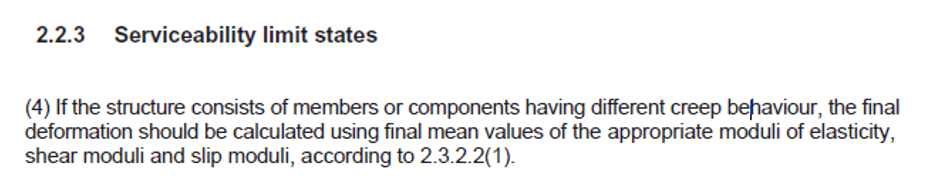
From here, further reference is made to 2.3.2.2, see excerpt below.
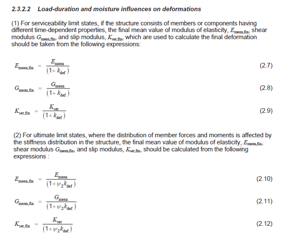
This method is used since it is impossible to keep the origin of the forces apart and calculate varying creep, which implies a varying stiffness, for different supporting parts in which the loads are distributed and where non-linear effects can occur. But according to 2.3.2.2, this is not required; instead, we can use either (1) kdef or (2) factored with psi2 * kdef.
FEM-Design Wiki
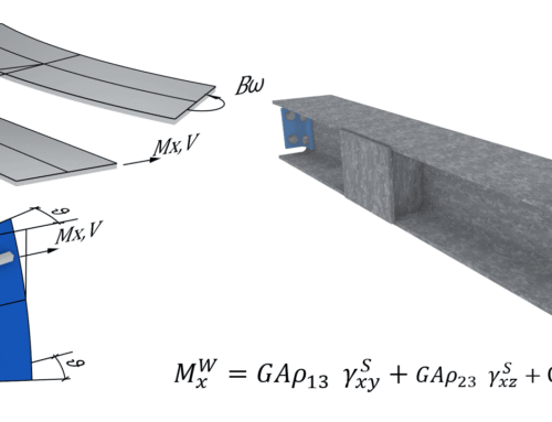
Full technical details and the theory can be found on the FEM-Design Wiki by clicking here.