Fyns Sommerland is an amusement park in Aarup, Denmark, featuring a 17-zip line complex. The current owners contracted the engineering firm J&P to provide the engineering calculations, drawings, and necessary permits. J&P used FEM-Design, our main structural calculation software, for this project.
Project overview:
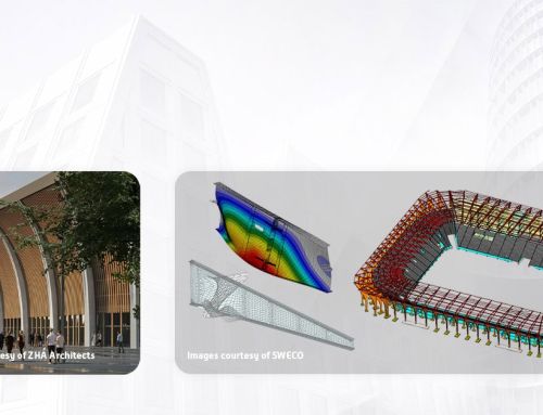
The zip line attraction features a central wooden tower constructed around four Douglas pine poles, rising to a height of 17 meters. This tower has five levels of individual platforms that serve as departure and arrival points for zip-line users. The longest of these zip lines extends over 217 meters.
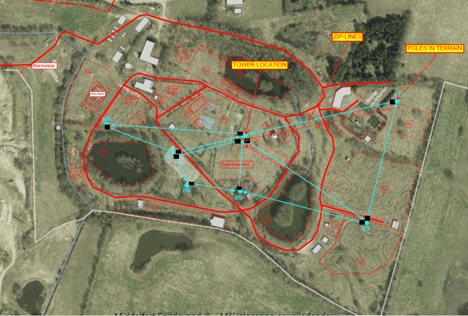
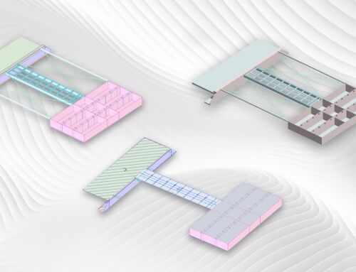
Situation plan. Image credit: J&P
The project’s main objective was to ensure the stability of the tower and the non-natural cable fixing points. The tower is supported by several guy lines, which stiffened it for wind load and the load exerted by the zip line wires. Further, the guy lines are anchored to 6 anchor points in concrete foundations on the ground, and the zip wires are tensioned to control the speed of the users. When used, additional tension is applied to the wires, resulting in horizontal dynamic loads on the tower depending on the number of zip lines.
The main challenges faced by the engineering team
The main challenge was to calculate the tower’s horizontal movements and determine the load on the foundations. It was necessary to set all combinations of the loads for the 6 zip lines on the tower and the bracing guy lines. The engineers used FEM-Design, our main structural calculation software, to solve these challenges.
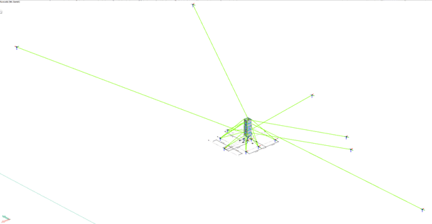
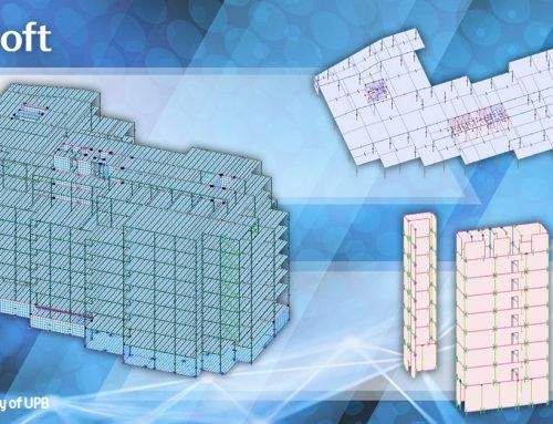
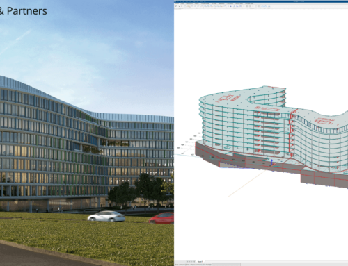
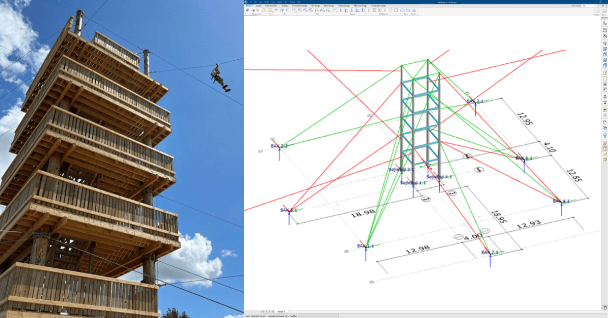
Tower with connected zip lines in correct levels. Image credit: J&P
“The tension in the wires increases because you have the dynamic loads of the person going down the zip line. I had to model all these combinations. In the start, I had all these pre-stress, not-in-use wires in the model as separate forces, and then I had all the zips in use with the dynamic loads, increasing the calculation time. That was not very efficient, so I collected all these pre-stressed, not-in-use zip line forces to one case combined for the tower, and then I only used the dynamic load on the wires in use with these six different combinations. It was much easier for the design and resulted in a shorter calculation time. With these combinations, I could see the movement of the tower and, if necessary, correct the movements with the help of supporting wires,” says Erik Østergaard, consultant engineer for J&P and the project engineer for Fyns Sommerland.
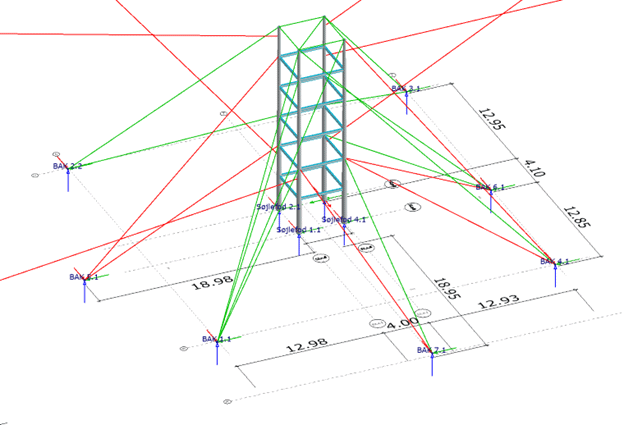
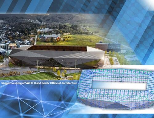
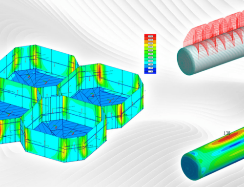
Tower with supporting wires. Image credit: J&P
The wooden tower was brought from another park, which posed another challenge. The team at J&P received only a simple situation plan in PDF format and a few Excel sheets without the structural capacity documentation. Based on the plan, the tower would turn sideways with six or seven zip lines connected, so the initial number of supporting wires was insufficient.
“In this context, FEM-Design is very good because you can model the posts and platforms and add the zip lines attachment points in the model on the tower. Moreover, the wires put in FEM-Design were attached to the poles and the tower. Because the terrain is not completely flat, the slope sometimes goes downwards to the tower; in other cases, it’s from the tower and down to the pole. So, to achieve the curve necessary for the zip line to work correctly, I paid attention to the simulation of the wires because the wires are pre-tensioned”, Erik adds.
Moreover, the park’s natural landscape posed other challenges due to the different heights of the natural Douglas fir trees or the non-natural poles that hold the arrival platforms. To tackle this, the team at J&P went into the field to determine the correct level of the connecting point on earth or the opposite stations based on the location of the large pool of Douglas fir trees.
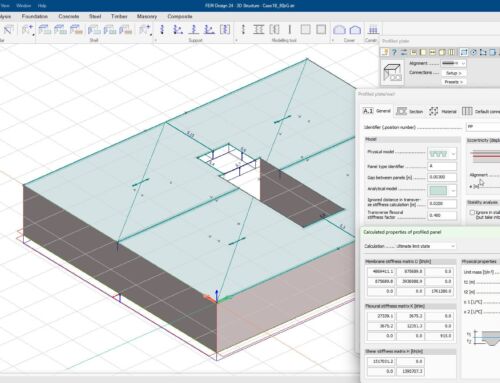
“The horizontal deformations were limited to a maximum of 15 millimetres. If the tower moves more, it impacts the lines on the other side. This is because the tension is higher, and then the normal curvature of the lines would disappear. Since we don’t know whether one, two or all zip lines are in use simultaneously, I used load combination generation in FEM-Design to control the deformation and determine the anchor forces,” Erik adds.
Next, they had to obtain a permit for the tower from the local authorities.
To meet deadlines and get the necessary permits before summer, the design and building process went in parallel with the engineering calculations. Due to the shifting positions of different objects, J&P engineers performed several recalculations during this process.
Why they chose our structural calculation software for this project
FEM-Design was selected for its ability to handle complex load combinations efficiently, provide an intuitive graphical interface, and manage the documentation of the results.
Our main structural calculation software enabled J&P engineers to automatically generate all the load combinations for the various scenarios and saved them time by simulating the impact of the zip lines on the tower and calculating the foundations for the guy lines 6 anchor points.
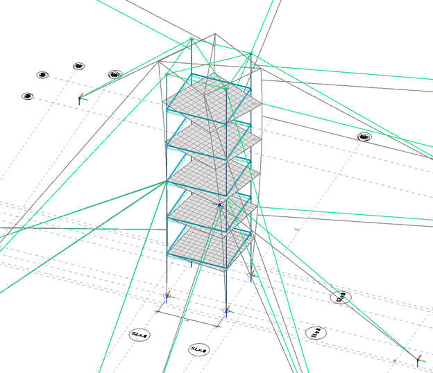
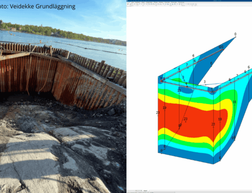
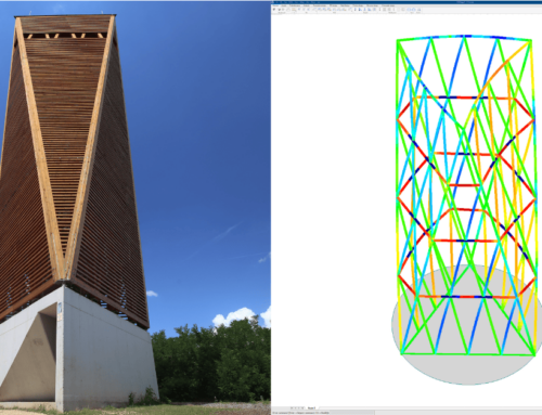
Overscaled deformations of the tower. Image credit: J&P
“Given FEM-Design’s benefits so far, we will use it for future projects. We have a large variety of calculations, and using FEM-Design is convenient. There are some very nice structural calculations we can do in FEM-Design. Moreover, FEM modeling facilities are nice and easy to use, and the documentation is helpful,” Erik says.
Erik started his journey with FEM-Design in 2011 and has remained a fan. He uses our structural calculation software for unique designs of concrete slabs and various steel constructions.
“The collaboration is good as usual. For example, for this project, I had a question about the compression force in the wires. If I used the force as a real force without any combination, there would be tension in the force that was not explainable. So, I submitted the model to the StruSoft support team. It was a convenient process, and I got the solution I needed,” Erik concludes.
Customer portrait: J&P
The engineering firm J&P provides consulting assistance for large and small building projects. Pioneering in engineering consultancy since 1999, J&P completed 4,000+ projects, defining precision through engineering calculations, certifications, drawings, and expert guidance.
Structural calculation software – every engineer’s friend
Take your structural engineering projects to the next level with FEM-Design, our versatile and user-friendly structural calculation software.