The Alfa Laval office building and laboratory project in Stockholm, Sweden, is a testament to the structural complexity and the power of FEM-Design in tackling complex engineering challenges for load analysis and more. As the trusted structural engineering software, FEM-Design played a crucial role in deciphering and resolving the various challenges faced by SWETCH, a leading structural engineering firm renowned for its innovative solutions.
Project overview and scope:
Spanning 35,000 square meters, the Alfa Laval office is a complex facility comprising office spaces and a high-tech laboratory for product development, testing, and innovation. Alfa Laval, a global leader in heat transfer, separation technology, and fluid handling, required a unique feature – a 20-ton rail-mounted crane within the new laboratory.
SWETCH was tasked with designing this project’s steel, composite, and precast reinforced concrete structures. Commencing in late summer 2022 and completing in spring 2023, the structural design process was intricate. Production and assembly swiftly followed, introducing additional complexities.
From the beginning, SWETCH opted for FEM-Design because they use it constantly in their projects.
“It was around 2015 when we first learned of a mysterious software being used in Sweden and Norway that is easy to work with and does the design according to Eurocode. We found out it was FEM-Design. We tested it and then jumped to use it for our next projects,” says Viktors Magone, structural engineer at SWETCH.
The challenges faced: load analysis, cantilevered section & laboratory assembly
FEM-Design played an essential role in tackling the project’s structural challenges. The primary focus areas included the complex load analysis for the foundation and a cantilevered section of the office building, as well as wind load analysis for the unique geometry of the laboratory.
FEM-Design’s advanced load analysis capabilities empowered SWETCH engineers to accurately calculate the loads on the foundation, the forces in structural members due to load distribution, the forces in joints and edge connections, and global displacements of the structure.
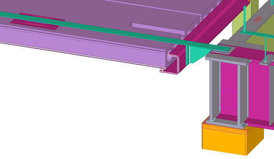
This project had some additional challenges – part of the office is cantilevered in a truss on the top floor. Therefore, the structure had to be propped by temporary columns during assembly because the truss hadn’t been assembled yet. This cantilever also shouldn’t deflect too much after removing temporary columns and from the loads introduced after the construction of the façade.
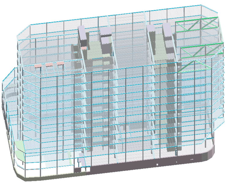
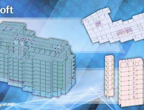
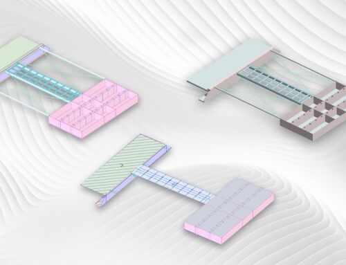
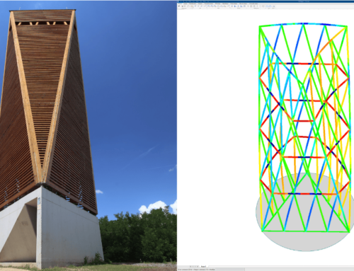
FEM-Design model of the Alfa Laval office building. Image credits © SWETCH.
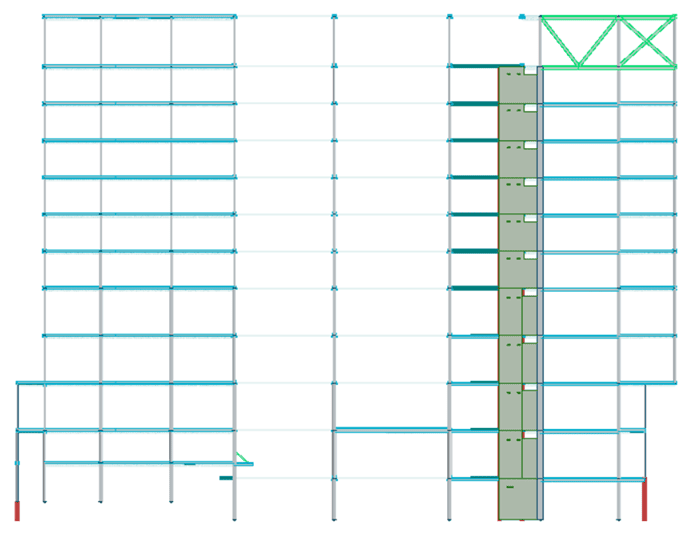
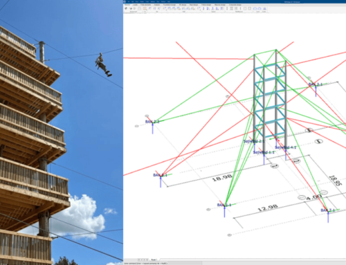
FEM-Design model of the office’s cantilevered section. Image credits © SWETCH.
Another complex engineering challenge in this project was assembling the laboratory in 5 stages while finishing the façade from bottom to top in each stage. This caused different wind load patterns and larger wind loads than in the final stage. Also, the stages were divided so that the first 2 didn’t have enough bracing members to ensure structure stability, so the laboratory had to be temporarily braced against the office building.
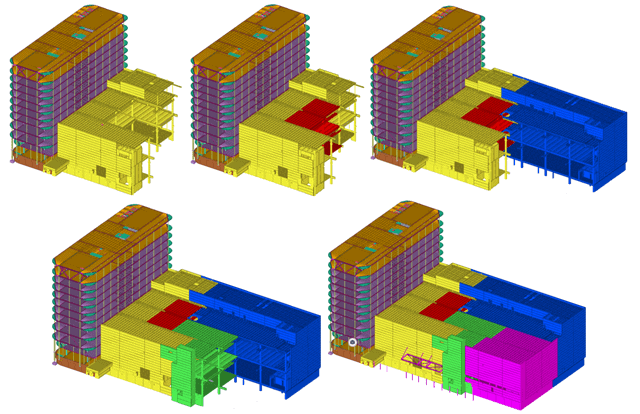
The five stages of the laboratory assembly. Image credits © SWETCH.
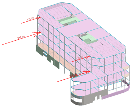
Lateral loads from stage two of laboratory assembly onto the office building. Image credits © SWETCH.
The temporary joints to brace the laboratory assembly stage two against the office building. Image credits © SWETCH.
“The complex geometry of the laboratory is due to crane beams located on two floors, which doesn’t happen often. Moreover, you don’t often see 22,000 kN reactions from just a 3-storey structure,” Viktors Magone adds.
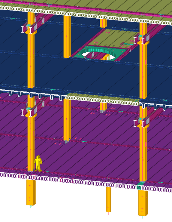
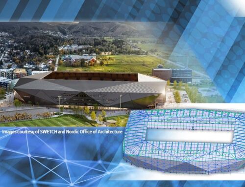
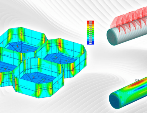
The geometry of the laboratory, compared to a 1.8-meter-tall human. Image credits © SWETCH.
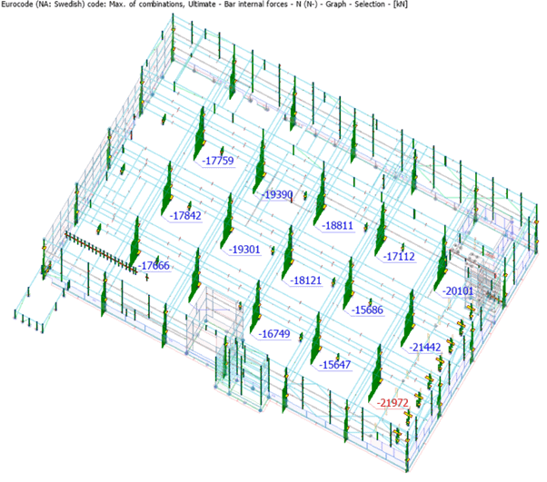
22,000 kN reactions from a three-story structure. Image credits © SWETCH.
Key features and benefits of using FEM-Design
FEM-Design showcased its capabilities in solving the complex engineering challenges for the Alfa Laval project.
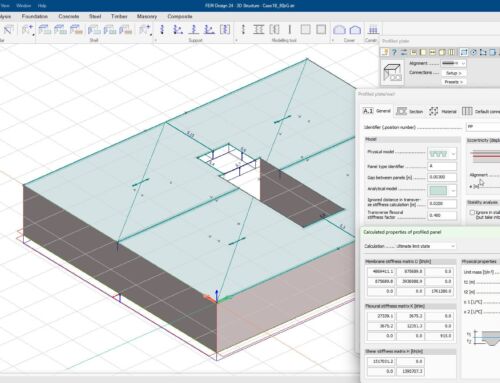
The engineers at SWETCH used IFC import to take raw input from construction elements done in other modelling software and use it as input for analysis in FEM-Design.
“It is possible to create such models swiftly using IFC import and then prepare them for loading and analysis within FEM-Design, using the ingenious tools for processing the raw geometry from Tekla Structures or other modelling software. Since introducing this IFC import feature in FEM-Design version 21, I have dropped the classic way of constructing FE models, and I don’t look back,” Viktors Magone emphasizes.
To enhance the model’s structural integrity, they used FEM-Design to check non-linear behaviour for supports.
Viktors Magone elaborates: “Another feature of high importance to us is the ability to make non-linear supports to avoid distributing tension into the foundations. For some projects, evading tensions in most of the wall edge connections is possible using non-linear properties.”
FEM-Design showed remarkable progress, with calculation speeds for non-linear load combinations doubling within two consecutive years.
Viktors Magone highlights this advancement: “I can say that doubling the calculation speed of non-linear load combinations in two consecutive years is quite impressive. The smaller projects can be calculated in 10-20 minutes even having loads of non-linearities in the analyses.”
Overall, FEM-Design has proved a reliable software in Viktors’ toolbox.
“The key strength is the effortless and intuitive user interface. The variety of modelling functions makes FEM-Design a better modelling software than software designed for only modelling. Another key strength is the communication between the developers and the users. The user feedback and improvement ideas are considered immediately. As a long-term user of FEM-Design, I am delighted to see the impact of my feedback on the software and how it develops,” Viktors concludes.
Workflow integration & prospects
SWETCH easily integrated FEM-Design into their existing workflow:
- Create the raw geometrical model in Tekla Structures;
- Import the IFC of the structural geometry into FEM-Design;
- Prepare the analytical model, calculate and fine-tune it to pass the global checks;
- Continue calculating members and joints following the forces in the global model.
The future holds promising prospects for SWETCH’s continued use of FEM-Design. They aim to leverage the upcoming features in their future projects.
“We are happy that we participated at the KCT event this year. We have shared our list of ideas at the event,” Viktors Magone adds.
Customer portrait:
SWETCH is a civil engineering firm from Riga, Latvia. It was founded in 2015 and focuses on reinforced concrete and steel construction design. They have done various projects, such as schools, hotels, residential buildings, universities, and business offices.
As a seasoned structural engineer, Viktors Magone brings a wealth of expertise. He has refined his skills in creating finite element (FE) models and designing structural steel and precast concrete members and joints.
Discover how FEM-Design can help you with complex engineering challenges
Discover more details about FEM-Design here. If you’re unfamiliar with the software, you can always start with a free trial to see if it fits your needs. We look forward to seeing the unique projects you’ll do with FEM-Design.