Answers to common questions about 7DOF torsional warping.
What is 7DOF or Torsional Warping?
Torsional warping is a phenomenon that happens to all real beams except circular sections. Torsional warping occurs in all engineering materials, such as concrete, steel, timber, and aluminium. Torsional warping occurs only when a beam is subjected to torsion. Elements under compression or bending, or a combination of those, do not warp. When there is no torsion in the elements, a standard 6-DOF (Degrees of Freedom) model is sufficient. When there is torsion, and the section is something other than a circle, and torsion is prevented, torsional warping happens, and 7DOF is required.
Torsional warping can be described by adding a new degree of freedom to beam models. This 7th degree of freedom also has a new internal force – bimoment B – and a new 7th deformation component – warping or ϑ. These beam models that have 7 degrees of freedom are called 7DOF beams.
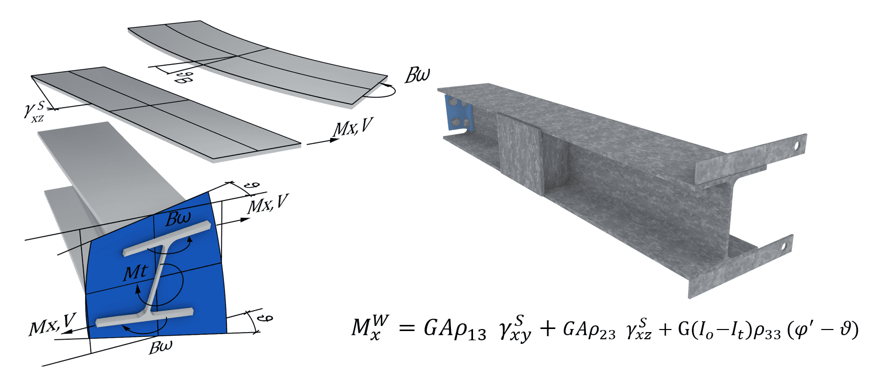
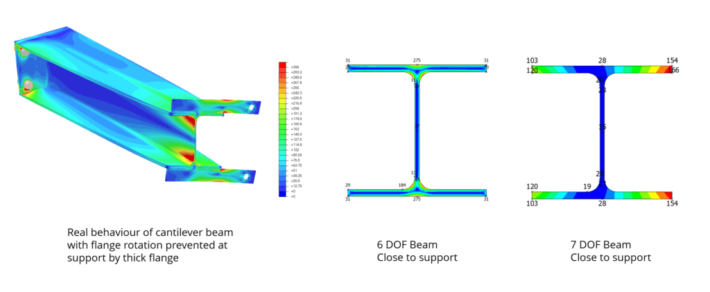
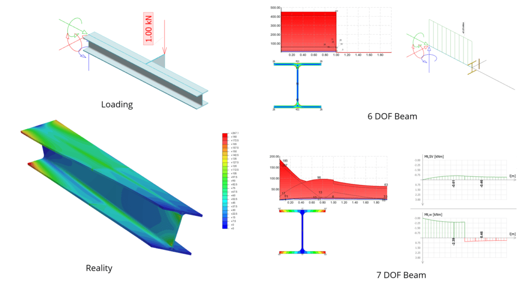
Torsional warping is easier to understand if you think about the behaviour of I-beams. I use this analogy a lot. When you twist an I-beam, two phenomena happen. Torsion causes shear in the beam walls, and if flange rotation is prevented at some point, flange bending stresses in the beam’s longitudinal direction and flange shear stresses in the transverse direction occur. A 6-DOF beam neglects flange bending and shear effects and therefore is an incorrect model for beams under torsion. A 7DOF beam can describe this behavior very accurately and therefore matches reality.
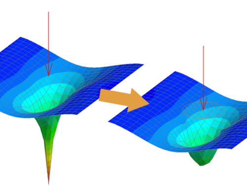
7DOF beams explain stresses caused by torsion much more realistically – look at the picture below and compare St. Venant stresses to total torsion stresses – there is hardly any correlation. Also, a 7DOF beam model provides the correct torsional stiffness to beams. The error with 6DOF beams can be up to 500%.

FEM-Design General 7DOF – Is it Different Than Other 7DOFs?
You have probably seen diagrams of theories in which sections are represented as a collection of lines when torsional warping is explained. Approximating the section wall with lines simplifies the calculations for section warping properties such as omega and warping functions. If you take a closer look at the theories, you see that warping deformation is explained only by bending of a collection of these section lines.
If we take an I-beam as an example, warping is explained by the bending of the top and bottom flanges in the horizontal plane. This theory is called Vlasov, and it describes warping when the section is an open section (not a tube), and the walls are thin. This is the most common 7DOF theory in FE software. Vlasov is a good approximation when span lengths are long and walls are thin.
When span lengths get shorter, shear deformations cannot be neglected anymore and Vlasov theory deviates from reality – usually to the unsafe side. Shear deformation of flanges in warping causes a loss of warping stiffness. Kollbrunner theory adds shear deformations to warping. Shear deformation becomes essential when torsional warping of tubes or sections with tubular parts is analyzed. Shear becomes a more important component of warping.
FEM-Design uses the so-called modified Kollbrunner theory. The weakness of Kollbrunner theory is that it assumes a very simple shear stress distribution which can only be found in thin walls. Therefore, it does not suit the analysis of massive solid sections like concrete or sections with thick walls. FEM-Design adds a new shear stress correction factor ρ33 to the stiffness matrix to handle the complex shear stress state of these solids in warping and therefore also allows thick-walled closed sections.
Warping happens in all sections and FEM-Design supports arbitrary sections – so the general 7DOF theory also accepts any section. This is a general theory for warping.
Read more in the theory manual here.

Benefits of FEM-Design General Torsional Warping Model:
- Allows any section, including closed sections
- Warping effects of all sections in all structures
- You no longer have to guess the effects of 7DOF if your software only accepts thin-walled open sections
- Any material; stress analysis is based on isotropic material
- Bimoment peaks are reduced – more realistic stresses compared to Vlasov
- More realistic lateral torsional buckling modes – Vlasov warping gives lateral buckling modes on the unsafe side because it lacks shear
- 7DOF theory is compatible with 6DOF theory, which also has shear deformations
- More accurate in short spans
- More accurate bimoment decay – more is carried by St. Venant torsion
- Second-order elements are very accurate even with just a few FEs
6DOF Safer Than 7DOF?
Often the first reaction to 7DOF is complexity – it is seen as something that is hard to grasp. The immediate reaction is then to use the “safe” 6DOF beams which the user has always used. The unfortunate news is that the safety of 6DOF is a false statement. 7DOF beams are always more realistic. A more realistic system response reveals the true weak points of a structure.
In some points of a structure 7DOF is safer; in some points 6DOF is safer. The only thing that is certain with 6DOF is that you are further from reality. So actually, 7DOF is safer. It is not justified to forget a real and essential part of beam mechanics if you do not know anything about it or you dislike it.
When you choose 6DOF over 7DOF, make it a conscious choice. When you choose 6DOF over 7DOF, you are making the following engineering assumption: torsion is free torsion, and this section does not warp.
See also: “Free torsion – Prevented torsion” and “When should I use 7DOF?”
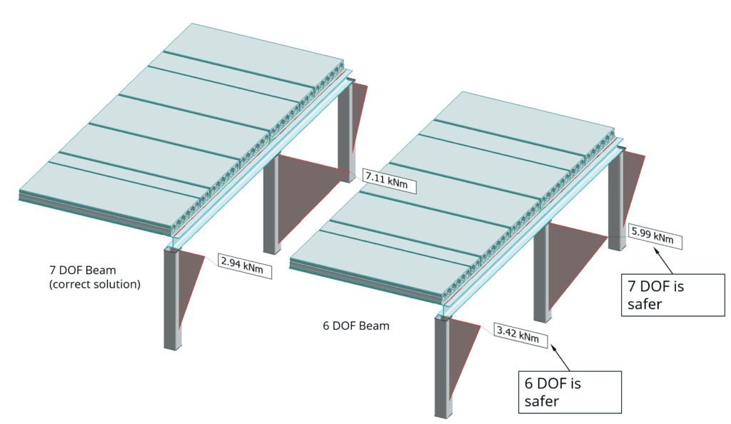
Example: How 7DOF affects load distribution. Design of columns for bending and design of column bolt joint to beam with eccentric hollow-core load. Only 7DOF can give the right load distribution. 6DOF is not safer. Assumption of free torsion is wrong here.
So can I now change all my beams to 7DOF?
With FEM-Design’s general 7DOF, you really have this option to turn it on for every beam in your model – all 500 of those. Pretty good? But is this a smart thing to do? Would you drive a four-wheel drive on the highway in summer? You can, but it’s not smart. 7DOF adds 2 new rows to the stiffness matrix. This means that every node coupling to all other nodes in the model must be represented in the stiffness matrix using the new 7th freedom. So it means longer calculation time and a more complex FE model. The computational penalty is small on modern computers, especially compared with shell-model beams, which are much slower and almost impossible to produce at a large scale.
The biggest issue with the “default” 7DOF beams is that they are unnecessary in most cases. Seldom do beams exhibit torsion or hard stability problems that require a 7DOF solution. Save 7DOF for those beams where it’s really needed. And remember the common wisdom with FE models: if your boundary conditions are incorrect, your model is incorrect. With 7DOF, this means you need to define 7DOF connections for all your beams – all 500 of those – and set 7DOF properties for all your supports. It is not enough to “turn on” the model and assume it is better now. It’s not worse at least. But also keep in mind: use of 6DOF beam also should be a conscious choice – not the result of lack of motivation to define 7DOF boundary conditions. See question “Is 7DOF safer?”
Is this the same as the St. Venant-Vlasov torsion?
Sometimes torsional warping is called “Vlasov torsion”, and this is quite a common term in Sweden. However, Vlasov is not a particularly useful term for torsional warping, as it is only one of the theories and a limited one. For long beams with thin walls, FEM-Design theory yields results very close to Vlasov theory, whereas for short beams with thick-section parts, FEM-Design theory is more accurate. See “FEM-Design General 7DOF” question above. However, the model is mixed torsion, so it handles both the St. Venant part and the “Vlasov” part.
When should I use 7DOF?
In theory, this is simple: there are just two use cases, but in practice, this is more complex and nuanced. But let’s look at the basic principles here. Use cases include torsion analysis of sections other than circles and lateral stability analysis of beam models in complex cases; in simple cases, you can use FEM-Design steel design to check lateral stability.
The first use case is torsion analysis of any beam other than circular sections. The first condition under which 7DOF yields different results than 6DOF is prevented torsion. Often in practice, if you are uncertain whether torsion is prevented or not, assume torsion is prevented. 95% of real beams have prevented torsion – even if you think it is free torsion, and you do not have any warping supports, think again. See next question “What is prevented torsion?”
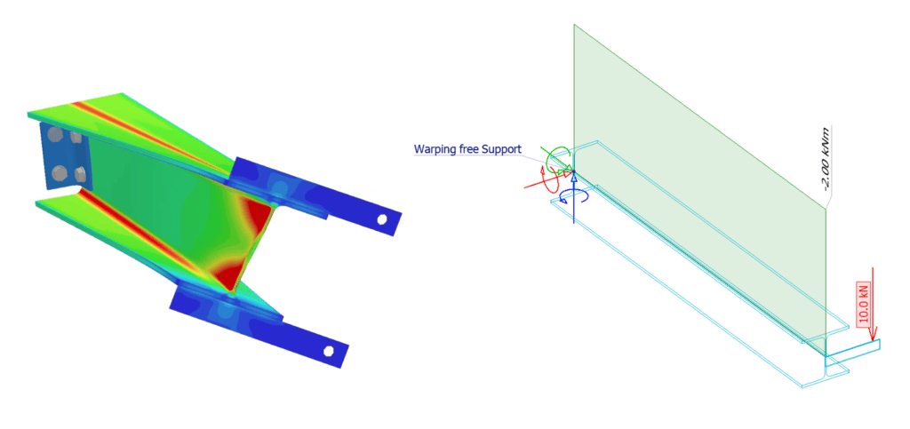
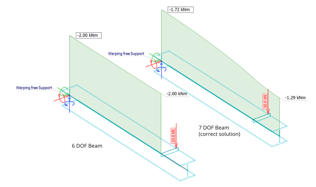
An example of torsion analysis of a doubly symmetric section. Only the 7DOF model produces internal forces which give the right internal stresses. Also, the 6DOF beam gives 500% error in deformation.
When doing torsion analysis on unsymmetric sections and channels, 7DOF really shines. A 6DOF beam twists without any lateral movement. Torsion and lateral movement are uncoupled. When unsymmetric or doubly unsymmetric sections are under torsional load, they deflect sideways. Only 7DOF can describe this. Another benefit of 7DOF is the ability to define the exact load location. See question “Why do I need to set load location in 7DOF?”
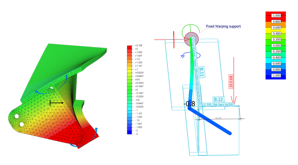
An example of torsion analysis of an unsymmetric section. Warping produces internal bimoment, which is mostly carried by flange bending sideways. Due to flange unsymmetry the beam moves sideways under pure torsion – one flange has less stiffness.
When can I use 7DOF?
When should you use 7DOF, and when can you use it? 7DOF is beam theory. Beam theory has limitations. In beams, stresses are only present in the beam’s length direction and in perpendicular shear, according to a simplified model. When the beam span is very short, the beam theory stops working, and it’s a 3D problem. Limitation of FEM-Design for beam length in warping is shorter than in other software due to the general theory (modified Kollbrunner). Because beam stresses are along the length, 7DOF cannot predict behaviour directly under point loads or point supports. So those stability problems cannot be handled by 7DOF.
If a beam has a high, thin web, the cross-section can buckle due to section-shape distortion. 7DOF assumes that the section remains the original shape. When wall thicknesses are very thin, and section parts are wide, shear lag effects become significant. 7DOF assumes constant stress distribution of plated parts under bending – no shear lag. Then the beam theory is no longer applicable. In beam joints, so-called discontinuity regions, the 7DOF stops working.
In a nutshell, 7DOF suits problems which can be described by beam theory. Beams are long, and their cross-sectional shape remains constant without distortion. 7DOF models the lateral stability of beams but does not account for local effects such as buckling at supports. Add web stiffeners at supports and under point loads to prevent section distortion and ensure the 7DOF theory applies. Do not use wide and thin-section parts in bending loading.
What is prevented torsion?
7DOF is mandatory for preventing torsion. So what is free torsion? The definition of free torsion is that length-direction distortions caused by torsion can occur freely. A common misconception is that when you do not have warping supports or flange rotation is not prevented at any point along the beam, the beam is free to twist. This is a false statement. Let me explain: This is what free torsion looks like: a cantilever beam and a load at the end – torsion is constant in the beam, and flanges are free to rotate.
Free torsion, reality and beam model presentation. Constant torsion Mt,SV moment of beam without any warping supports. 7DOF and 6DOF agree.
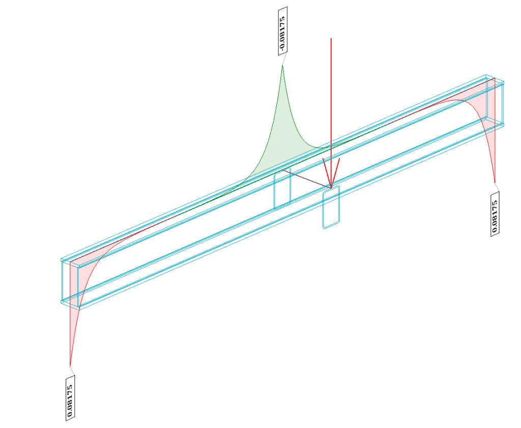
When any of those two conditions – constant torsion and free flange rotations of an I-beam – is not met, it’s prevented torsion. Let’s do a small modification to the model. Let’s add one free section to the beam end. Now, torsion is no longer constant. The end part of the beam does not have external torsion. This means the flange has to have curvature since the loading on the flanges changes along the beam (torsion changes). Curvature of flanges produces torsional warping stresses, and it is no longer free torsion, and only 7DOF can give the right results.
Modification to beam model above. St, venant torsion of beams. Even without flange supports at beam ends flanges have curvature. This means that Warping forces developes and warping is also carrying load – and this is prevented torsion.
If all this is too much to take in a single instance, remember: just set warping supports to match reality at beam ends and turn on the 7DOF model in FEM-Design, and the software will give you the right solution always – whether it’s free torsion or prevented torsion. Your job as an engineer is to set the right boundary conditions, and the general 7DOF model handles the rest. And now you know, preventing torsion is not about boundary conditions – it is about beam flange curvature. When flanges are a straight line in torsion deformation, it’s free torsion. And 95% of real-world cases are prevented torsion. Just turn on 7DOF, and you are good to go.
What is warping support?
Most of us have handled supports for normal beam models throughout our engineering careers. We know what a moment-rigid column baseplate looks like – a thick flange with anchors outside of the column and preferably baseplate stiffeners. But what does a rigid warping support or warping boundary condition look like?
The answer is quite simple for I-beams. If the rotation of both flanges about the beam’s vertical axis is prevented at the beam end, the beam end is a warping support. If only one flange rotation is prevented, it is not a warping support – bimoments need two flanges. For solid sections like timber shapes or concrete sections, you can think of it as beam corner fibres locking in the beam length direction. If a concrete beam is anchored to support at all corners, it is a warping support. In FEM-Design, setting the warping supports is easy. A warping spring (typically fixed or free) can be set to a point support group or by using a point support where a pure warping support is located.
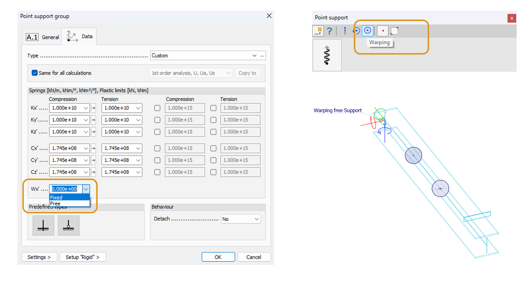
Handling of warping supports in FEM-Design general 7DOF model. Point support group has Wx and point support has warping-only support. All supports can be set directly in 3D view by clicking, so definition of 8 web stiffeners to 4 different beams should not take more than 30 seconds. Warping supports can be copied from beam to beam in 3D view or deleted or moved or modified with any edit operation. This is fast and efficient.
Unlike normal beam supports, these warping supports can be located at the mid-point of the beam without any connection to the surrounding world. A bimoment is a self-balancing force system. In other words, the sum of moments and forces is zero in every cross-section of the structure from bimoment. Warping support basically means support against warping deformation. Flange rotation can be prevented entirely or partially. Partial warping support requires calculating the warping spring. This is a spring value which prevents warping deformation. For I-beams, this is the spring value that prevents flange rotation about the vertical axis, taking the beam height into account. Stiffeners, such as the one on the right side in the picture below, can be used to increase the lateral torsional buckling capacity of the beam. 7DOF accounts for this support in stability analysis and also increases torsional stiffness.
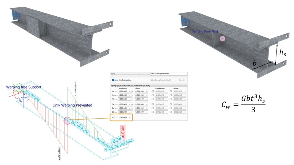
Modeling of warping supports in FEM-Design. Warping support can also be located mid-beam. Example of rigid warping supports and semi-rigid warping support. Any combination of plates which fixes flanges together is a warping support.
No warping support reactions?
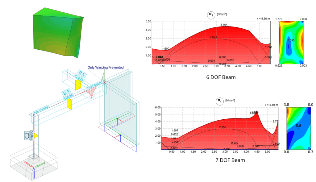
Bimoment is an internal force of the beam model. Bimoments are a self-balanced force system in every cross-section. It does not produce external moment or external force – the net force outside the beam section is zero. In the I-beam case, it is roughly two equal but opposing moments. In this sense, 7DOF does not have support reactions. This does not mean that bimoment (see question “What is bimoment”) should not be taken into account in design – absolutely it should!
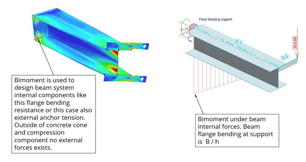
Example how system internal bimoment is taken into account in system internal steel component design.
What is bimoment?
Bimoment is the 7th DOF internal force in the beam model, causing warping. As the name suggests, it is two moments with different signs. They are equal and affect different flanges. This simple definition of bimoment allows you to calculate flange bending by dividing bimoment by h, the distance between flange centres. Simple as that. This definition allows you to perform hand calculations of bimoment using bending theory. You can also predict bimoment shapes based on simple beam bending tables. You can also estimate the bimoment magnitude and span, and the field moment ratios. Just keep in mind that St. Venant also carries torsion. So the higher the wall thicknesses, the less it’s like simple beam bending. Closed sections – it looks nothing like bending theory.

Simplified model for bimoment. Bending of flanges. This works roughly only for I-beams.
Well, I lied. This is not the definition of bimoment, in the general sense at least. The previous definition only applies to I-beams. Single or double symmetry; even with those, it is off a bit. The real definition of bimoment is a force which causes warping. It is bound by an equation to warping stiffness Iω and warping deformation change, just like the bending of a beam is bound to the second area moment and curvature of the beam axis. If bending doubles, curvature doubles. If the bimoment doubles, so does the first derivative of warping. If the warping stiffness is half, the warping change per unit length is double. Warping happens around both axes y and z. Also, the bimoment affects around both axes y and z. In other words, bimoment has no specific direction, and warping has no direction. It is not a vector like the first 6 DOFs.
If this sounds too complicated, think of bimoment as the sum of bending moments acting on all beam fibres about both axes. Warping stiffness quantifies the magnitude of a cross-section’s resistance to warping deformations about both axes. For I-beams, it becomes a pair of vectors and a pair of flange stiffnesses, since the major part of I-beam stiffness comes from the flanges, and warping effects in the other direction are very small. For those who prefer exact definitions, I apologise. I used the terms “vector” and “direction” loosely here to make this explanation easier to understand. However, warping lacks direction. And this becomes useful when you try to understand how warping propagates from beam to beam.
Why do I need to set the load location in 7DOF?
In a 6-DOF beam, the load acts at the beam’s centre of gravity. Vertical load does not cause rotation, and torsion does not cause lateral deformation. Sounds logical unless you think of channel sections. The channel torsion centre, the point where you place a load which does not cause rotation, is behind the back of the profile. In a 6DOF model, vertical load on a channel does not cause rotation. You might think you can fix this issue by applying a continuous bending moment to the beam, but that approach does not work because it introduces a new problem: beam rotation. Only a 7DOF beam can solve this dilemma. Load at the centre of gravity should not cause a support reaction, since the beam is connected to the surrounding structure at the centre of gravity; however, the beam should still twist. A 7DOF beam does that, but a 6DOF beam bends down.
For loads, FEM-Design allows you to specify a bounding box and an offset relative to it. If the load is placed 150 mm above the beam top flange and applied to beams of different sizes, it is always 150 mm above the beam.

6DOF beam vs 7DOF – load and beam location. FEM-Design now offer stools to adjust load location with special points, bounding rectangle and offset from that. Load location does not affect to loads connected to shell models or 6DOF beams.
7DOF model also allows moving load in the vertical direction. This has the same meaning as load location sideways – torsion in the beam with lateral loads. But the most important reason to set the load location vertically is stability analysis. The higher the load is placed, the lower the lateral torsional buckling mode. This effect is illustrated in the image below.
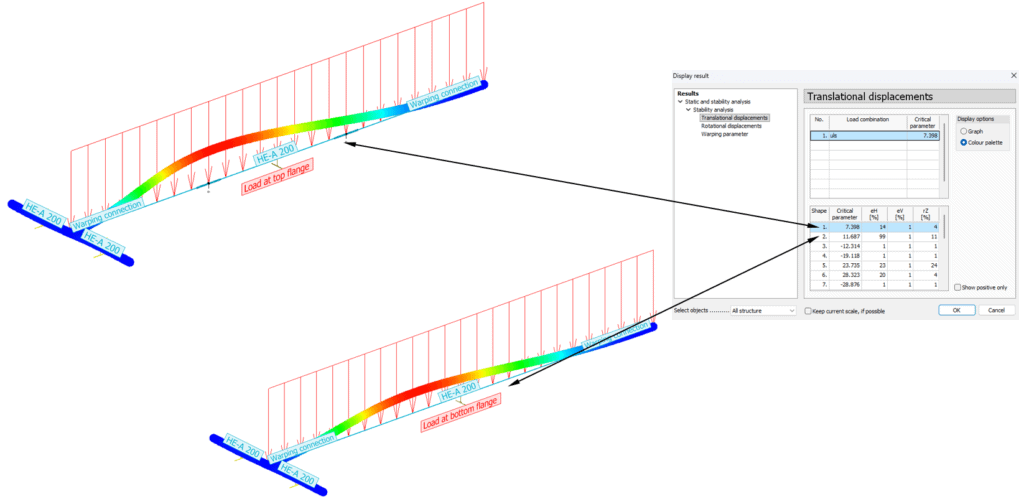
Load vertical location effect in eigenvalue solver (Stability). Higher load level decreases buckling factors – as it should.
Professor X says squares or angles or closed sections are “warping free”?
There is no single theory for torsional warping. Some theories model sections only as lines without any thickness. When defining omega diagrams or warping diagrams, these section parts have bending stiffness only around one axis. This theory, however, gives roughly the right solution when wall thicknesses are very small. In reality, section walls always have thickness, and therefore the warping function cannot be zero. Angle warping stiffness is small, but it is not zero. When sections are modeled as area objects instead of lines, warping coefficients (stiffness) can be defined for any shape. If you open the FEM-Design section editor and draw an angle, or check the warping stiffness of an angle, you can see that it has resistance to warping, which is the correct result. The same applies to square and rectangular shapes.
Solid sections which are more or less close to circles being “warping free” is simply false information. Clearly these shapes develop length-direction stresses under pure torsion. However, we can say that warping effects are very small for squares. Warping effects are local and occur close to warping supports, torsion supports, or point moments. These shapes have high St. Venant stiffness and low warping stiffness. The square root of the ratio St. Venant stiffness / warping stiffness is called the decay factor, and the decay factor tells how fast the bimoment decays. The universal answer here is that in reality only circles are warping free – all other sections warp, more or less. When St. Venant stiffness is high compared to warping stiffness, warping effects are very local. When warping stiffness is high and St. Venant stiffness is lower (like wide I-beams), then warping affects the whole beam.
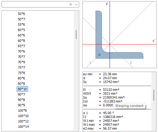
Warping of solid sections. Effects are local, but in some special cases, as illustrated above, warping effects produce meaningful effects. Usually 6DOF beams are good approximations of situations like this. Warping constant, Iw, of an angle section in FEM-Design.
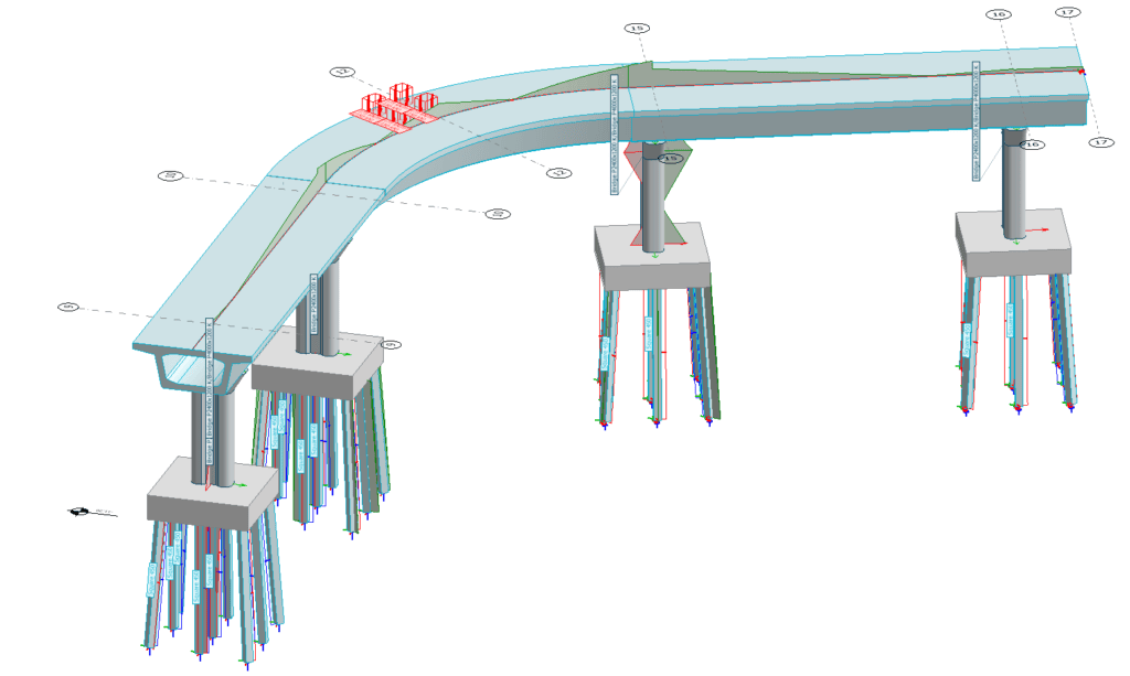
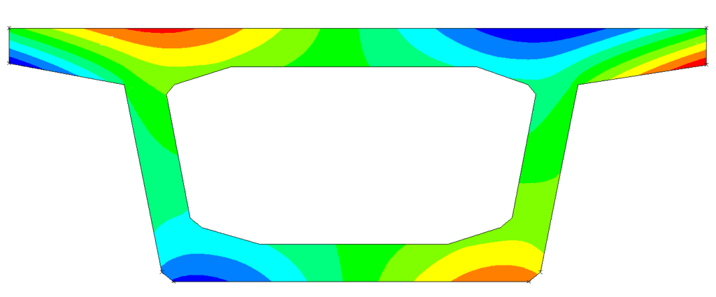
Example of closed section torsional warping. Stresses caused by bimoment. 7DOF has 20 % effect on stresses of bridge deck in areas close to piers and axle loads. Warping effects are semi-local – this section has properties of I-beam and box.
When 7DOF Is Really Important?
When warping stiffness is very high compared to St. Venant stiffness, the error between 6DOF and 7DOF can be huge. Errors up to 500% are not uncommon in deformations, and 50% error in stresses. 7DOF is the only viable torsional engineering model for I-beams, channels and similar shapes. Most of their torsion stiffness comes from warping and 6DOF is a totally false model.
The second case is bending of unsymmetric unsupported sections like channels. Under bending they twist and they have a loading dilemma; see “Why do I need to set load location in 7DOF”. When channels are supported laterally at both flanges to prevent torsion, they behave like 6DOF beams. When they have long free lengths, 7DOF can give results which are correct.
The third use case is lateral stability of any beam model. FE models do not simply give lateral stability loss modes in stability analysis if they are 6DOF beams. When you turn on 7DOF beams, they suddenly show stability loss modes.
Why do I see just a spike in B close to supports or loads?
If you apply general 7DOF to cases where 7DOF is not absolutely necessary (closed sections or solid sections), this phenomenon happens. Warping stiffness is small and St. Venant stiffness is high. The decay ratio is high. The general 7DOF model accelerates decay. This means that bimoment decays very fast close to supports and has only a local effect close to torsion point moments and supports. This is how it should work. It matches reality. I-beams and channels and similar shapes with two flanges produce smooth global bimoment shapes.
Spike-like bi-moments – torsion analysis of welded thick walled box section. Decay caused by high St Venant and General 7DOF shear.
More FEs when using 7DOF?
In mixed torsion – beams which carry torsion by two mechanisms – St. Venant and warping – it’s a balance between those. Warping is more bending-related but also shear-related (general 7DOF) phenomenon. On the other hand, St. Venant is pure shear. Under constant torsion, shear deformation per unit length (St. Venant) is constant. On the other hand, flange curvature change is proportional to distance from support. This means that these two change at different rates. How much St. Venant is carrying and how much warping is carrying changes constantly along the beam axis. This means that we have to add FE nodes to better understand how this interaction is happening along the beam.
With normal 6DOF we do not have this problem since all 6 DOFs are independent of each other in linear theory and we already know functions for how they change between nodes with basic cases like constant load or end moments – those beam bending tables. With 7DOF we do not have that luxury.
FEM-Design uses second-order FEs to predict more accurately the change between nodes. This means that general 7DOF beams are very accurate, or very close to the final solution, even with few FEs. FEM-Design has preprocessors and postprocessors. This means that load locations and support locations get FE nodes automatically, so it’s very hard to produce an inaccurate model. FEM-Design 7DOF models converge very fast to the final solution when more nodes are added. Below is an example of that. When you are calculating stability analysis and want to find flange lateral stability modes, it’s the same thing – you need at least 5 nodes per buckling length to make the analysis very accurate.
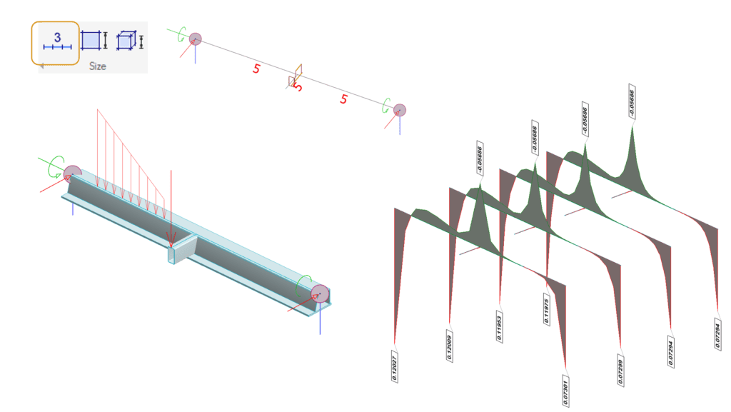
Deltabeam torsional warping analysis before casting. Eccentric load to flange and cantilever. beam FE division in FEM-Design. Right: bimoments of closed section. Convergence of General 7DOF. With just few FEs solution is very close to final solution. Beam FE division of beam sections from left to right 2,3,4,5.
How do I use 7DOF? Do I need a license?
Unlike other software, General 7DOF in FEM-Design is not a separate thing which needs to be turned on in settings. It is not its own license. All steel license holders get this feature, and all others can do one 7DOF beam. Any beam, any material and any shape in any model.
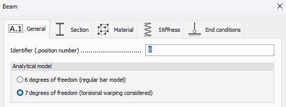
In beam settings there is a beam type: 6DOF or 7DOF. After that, beam start and end warping transmission couplings need to be defined. See “7DOF beam connections” below. This all probably takes a few seconds, and 7DOF can be set to hundreds of beams simultaneously. What else? Set 7DOF supports if warping is prevented at some points. See question “What is warping support?”. Set load location sideways and height direction. That’s it – press “Calculate” and you see results.
On the results side you have a new deformation component – warping parameter. This is a normalized measure of how much the section has warped from the initial state. The analogy in normal beam bending is deformation of the beam – the result of curvatures along the beam. Another result is bimoment B (see above). The torsion moment is divided into two components – St. Venant Mt,SV (shearing of walls) and Mt,W warping (flange bending & shear). Mtot tells total external torsion – sum of the two components. Please note that they can have different signs.
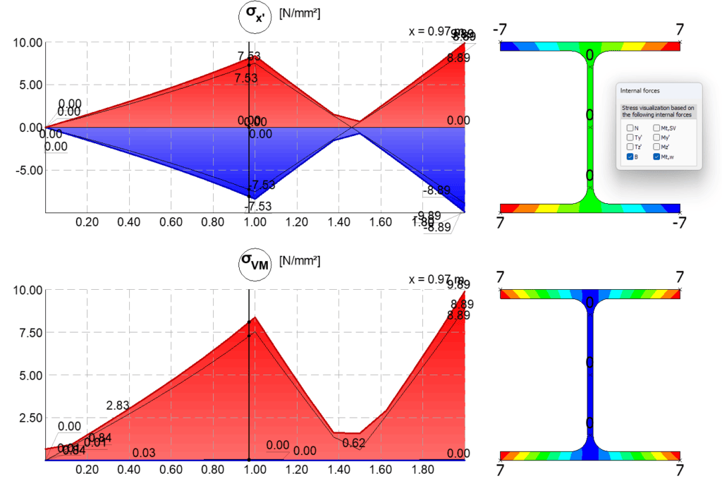

Torsional warping (7DOF) related results in FEM-Design, Example if Bimoment diagram and beam detail result of 7DOF internal forces. Detail stress results of 7DOF beam, user can isolate effects of bimoment and warping shear.
7DOF beam – stresses without external forces
This is quite a common case in a 7DOF model. In 6DOF models, when internal forces are zero, stresses are zero. This is a logical but wrong assumption. In 7DOF, warping and St. Venant can have different signs. This happens at every free end of a beam – a beam end where there is no support or torsion support. The end part of the beam does not have external stresses because forces cannot go to any support. But this does not mean beam flanges cannot have curvature in this region. See also “What is prevented torsion”. In this region, no external torsion is explained by two internal opposing mechanisms – St. Venant and warping. They cancel each other. See 7DOF chart below.
7DOF beam connections?
Torsional warping does not have a direction like traditional 6 DOFs, as discussed above. This means warping can be transmitted in beam connections independent of directions. But it is not so simple. And now I have bad news: this is not standardized like traditional 6 DOFs. EN 1993-1-1 gives you connection springs for bending moment transmission. And it gets even worse: there is not much scientific information about this topic. All studies are relatively new and are less than 15 years old. Also, papers do not offer a general solution to all possible connections with bolts and stiffeners – all those real things of connections.
7DOF transmission in beam connections is about beam corner translation mapping to translations of corners of another beam. If one beam corner moves in the beam direction by amount X, how much does the connected corner move in its own length direction, and in which direction (+ or -)? In the I-beam case it means flange bending transmission from beam to beam. The general solution can be complex, but a few rules of thumb can be made for practical engineering work. If beam flanges are in the same plane, flange bending moment caused by warping acts around the same axis. Then it is clear it’s only about flange bending transmission from flange to flange. Results are close enough to reality for design purposes.
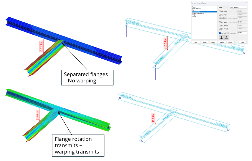
When flanges are not connected, warping transmission in a plane is weak from flange to flange. When flanges are connected, transmission is strong. Flange bending moments do not care about a 90-degree corner.

When only one flange is connected, bimoment cannot transmit (when bimoment is seen as a pair of equal moments). This happens when beams have different heights or only one of the flanges is connected.
Warping transmission becomes a more complex problem when beam flanges are no longer in the same plane. It is no longer a direct flange connection to each other. One beam’s flange bending moments have a different axis compared to the second beam. It is still about mapping of translations of one beam corner to another beam corner. Complexity here is that this mapping can produce negative and positive correlations – one beam rotates clockwise and the connected beam rotates anticlockwise. This kind of transmission can be described in 7DOF with a negative warping spring. This will flip warping and bimoment. This produces correct results and matches solid and shell models.
Also very typical for knee and T-type column connections is to lose a part of warping – connections are full of stiffeners, which act as partial warping supports. Arrangement of stiffeners makes it negative or positive transmission. There are a lot of unknowns here, and without a detailed model it is hard to quantify warping transmission strength. So it’s advisable to calculate both cases – stronger transmission and weaker transmission. If you have a detailed model of the connection you can study this mapping. And the same principle applies – if there is no connection between both flanges, it’s a warping-free connection.
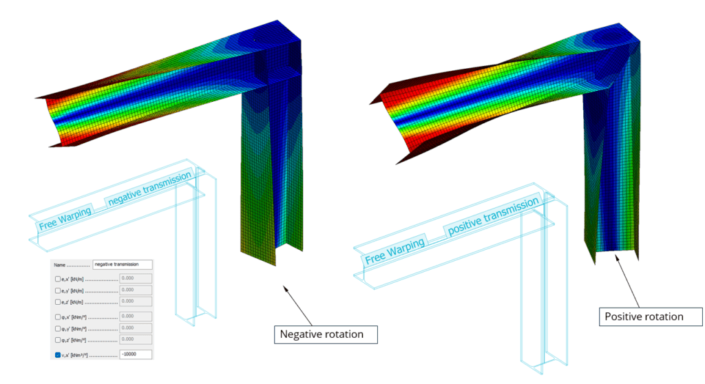
Mapping of corner rotation from beam to column. Left shows negative warping transmission. Right shows positive transmission. Both looses part of warping in detail. Right shows higher transmission. Example how 7DOF beam model with negative connection spring will flip bimoment and direction of warping in column – as it should. This example illustrates also how shell models can be used to study mapping and transmission. Without stiffeners both of these connections are warping free.
7DOF stability – how it works?
This blog post is not about matrix eigenvalue problems, so I won’t go too deep into details. All you need to know is: the eigenvalue solver (stability analysis) will give you eigenvalues of two matrices. Out come eigenvalues and eigenvectors. Eigenvalues physically represent the factor for combinations of loads at which stability is lost. Eigenvectors physically represent buckling modes. This is a linear system, so it only gives capacity of a perfect structure without even millimeter deviations, and material without yield limit, and beams without residual stresses. In practical terms, eigenvalue analysis compares node system compressions to node system lateral stiffnesses.
So this basic idea is the same with 7DOF. Eigenvalue analysis works exactly like with any other structure, except with 7DOF beams: compression of node systems is replaced by primary bending of beam FEs, and stiffness is replaced with warping stiffness and torsion stiffness. Out then come lateral stability loss modes of a perfect beam system.
This method to find beam lateral stability is very robust – like the beam model is robust. Weakness comes from boundary conditions and warping transmission between beams. You might think this transmission thing (previous answer) is not critical – think again. It directly affects internal forces, and also stability loss modes in stability analysis. If beam warping transmission couplings are not correct, buckling modes are incorrect.
A nice thing about 7DOF stability is its ability to solve stability of beam systems – no matter how complex the system is. It can also do things which no other finite element is capable of. Problems like timber beam stability: timber has relatively high warping stiffness, weak shear stiffness and weak torsion stiffness. Solid FEs are very hard to define so that they replicate this – also so that curved beam fibers follow the beam axis. For 7DOF beams this is very easy.
Stability of complex beam systems is an optimal place to apply 7DOF – Eurocode does not give critical factors for complex systems. Simple beams, on the other hand, already have good formulas, so use those Eurocode formulas instead. When you have critical factors for a 7DOF system you can proceed to Eurocode checks. You can use Eurocode general method for lateral stability or just use the 7DOF critical factor as a more accurate lateral torsional buckling factor. See question below about Eurocode. See also the question above about load level. Eurocode then handles all difficult things about residual stresses and initial curvatures and limited yield strength. Stability analysis is where savings with 7DOF mainly comes from. But it requires good understanding of boundary conditions and beam connections, or safe-side engineering assumptions of those.
7DOF vibrations
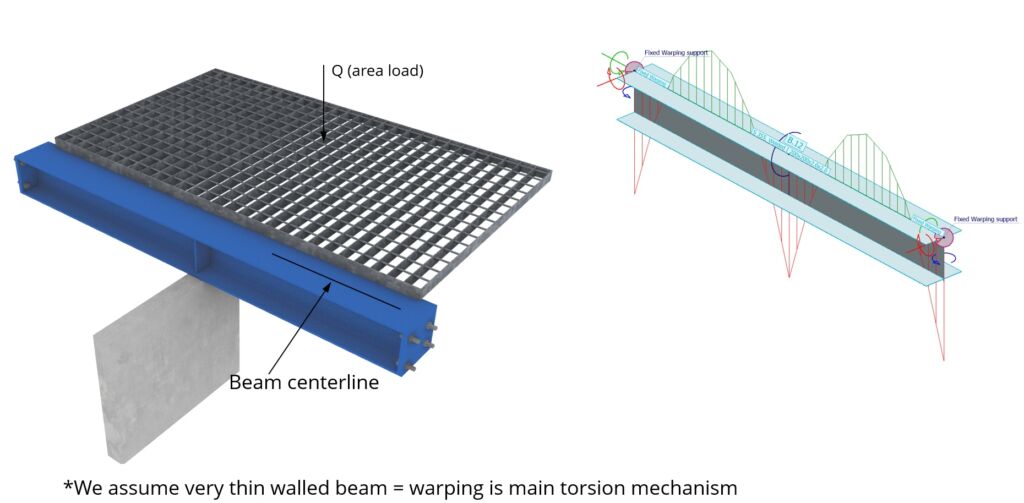
Quick guide to this is here. First you should know whether your FE software includes rotations of nodal masses or not. FEM-Design does not have rotational mass of nodes and so does not have point inertia. This means if you want to get torsional vibration modes of 7DOF beams alone, it does not work. Beams have point translational mass, so they do not have rotational vibration modes (I mean beams as isolated elements). But rotational stiffness is taken into account – also the 7DOF part. So if a rotational vibration mode manifests itself as translational vibration of nodes, it works. Bear in mind that if 7DOF beams are very heavy, their inertia is not part of the mass matrix. Usually this is not a big limitation, but it should be understood. Look at the picture below to get the basic idea. 7DOF beams of FEM-Design can be used as ribs of shell structures, so rib stability can be studied with an FE model.
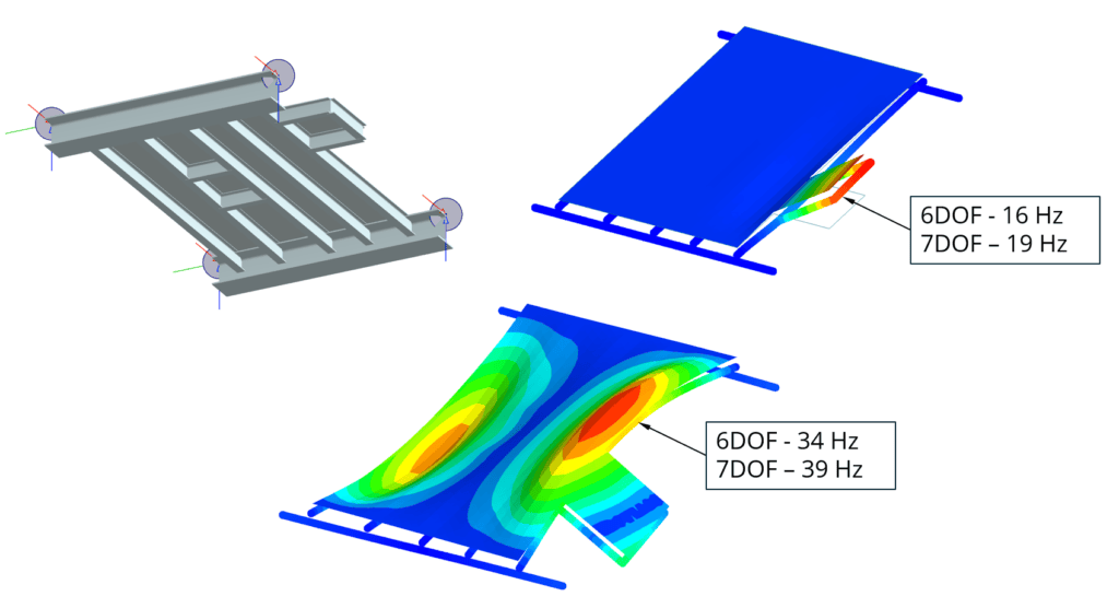
Vibration analysis of small steel deck. Torsion of 7DOF beams manifests itself as translational displacement of nodal masses of deck. Because 7DOF beams are stiffer in torsion - vibration modes are higher and more realistic
7DOF and steel design?
Not implemented yet. Right now it is a statics tool. Consideration of 7DOF in design of steel is up to the user.
How can you use 7DOF in design right now? First of all, you can calculate lateral buckling modes of complex systems of beams. See question above about stability analysis. EN 1993-1-1 check of FEM-Design already uses 7DOF-compatible formulas (warping) in lateral torsional stability calculations. This means that those standard hand calculation formulas already take warping into account. Calculation of simple beam lateral stability with 7DOF probably does not make sense – since you get the same result with more trouble.
For complex sets of beams with stiffeners, 7DOF can produce more realistic critical factors which can be used to adjust lateral buckling factors in steel design manually.
When there is an open section (or even a closed section) with a lot of torsion, the user can first do a normal steel check and do stress analysis afterwards to estimate how much warping can eat capacity – stress analysis allows isolating warping effects. Warping mostly interacts with bending capacity of the beam – it increases length-direction stresses. Close to supports it also adds lateral-direction shear stress in flanges. And in box sections also shear stress in vertical webs.
When you have 7DOF buckling modes you can verify your beam lateral stability and buckling and combined modes by Eurocode general method. This is easy to do even with Excel or Mathcad in 10 minutes. See EN 1993-1-1 6.3.4. If you do so, please note that you still need to do EN 1993-1-1 steel check in FEM-Design. Local buckling, shear buckling and stress interactions need to be done, and the general method is about lateral and combined stability only.
What are the limitations of the current model?
7DOF beams are not yet supported in non-linear analysis and material non-linearity is not supported. Another limitation is tapered beams. Only constant height beams are currently supported. Curved beams are accepted. Also specific analysis tools like camber simulation are not supported. Stiffness modifiers of beams are not currently supported.
What are upcoming developments of 7DOF?
We are planning to apply general 7DOF theory to tapered beams. Also because stress interaction of 7DOF to classical DOF is clear, we are planning to develop materially non-linear 7DOF. To better visualize the rotational nature of lateral buckling modes, we are planning to develop visualization routines. Because Eurocode 1993-1-1 G2 is very specific about use of bimoments, we are planning to implement 7DOF to steel design of Eurocode G2, including the general method. Also lots of other exciting things are coming.”

Blog post author
Joni Hytönen
Country Manager – Finland
Bio: Joni has helped and trained hundreds of engineers in structural analysis in Finland. He works in both civil and mechanical engineering fields with structural analysis. Joni has over 15 year of experience in structural design of many types and sizes of steel, concrete and timber structures. Joni is the Product Owner of our JIGI software and Country Manager for Finland. Please free to contact Joni if you need any help to solve your structural analysis problems.