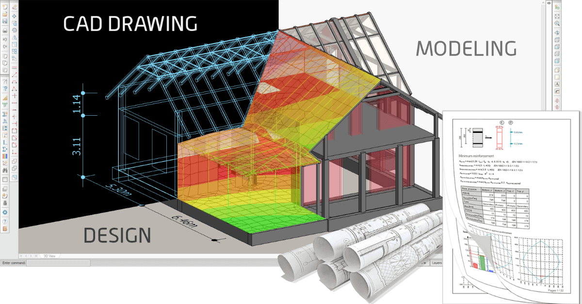
Frame Analysis
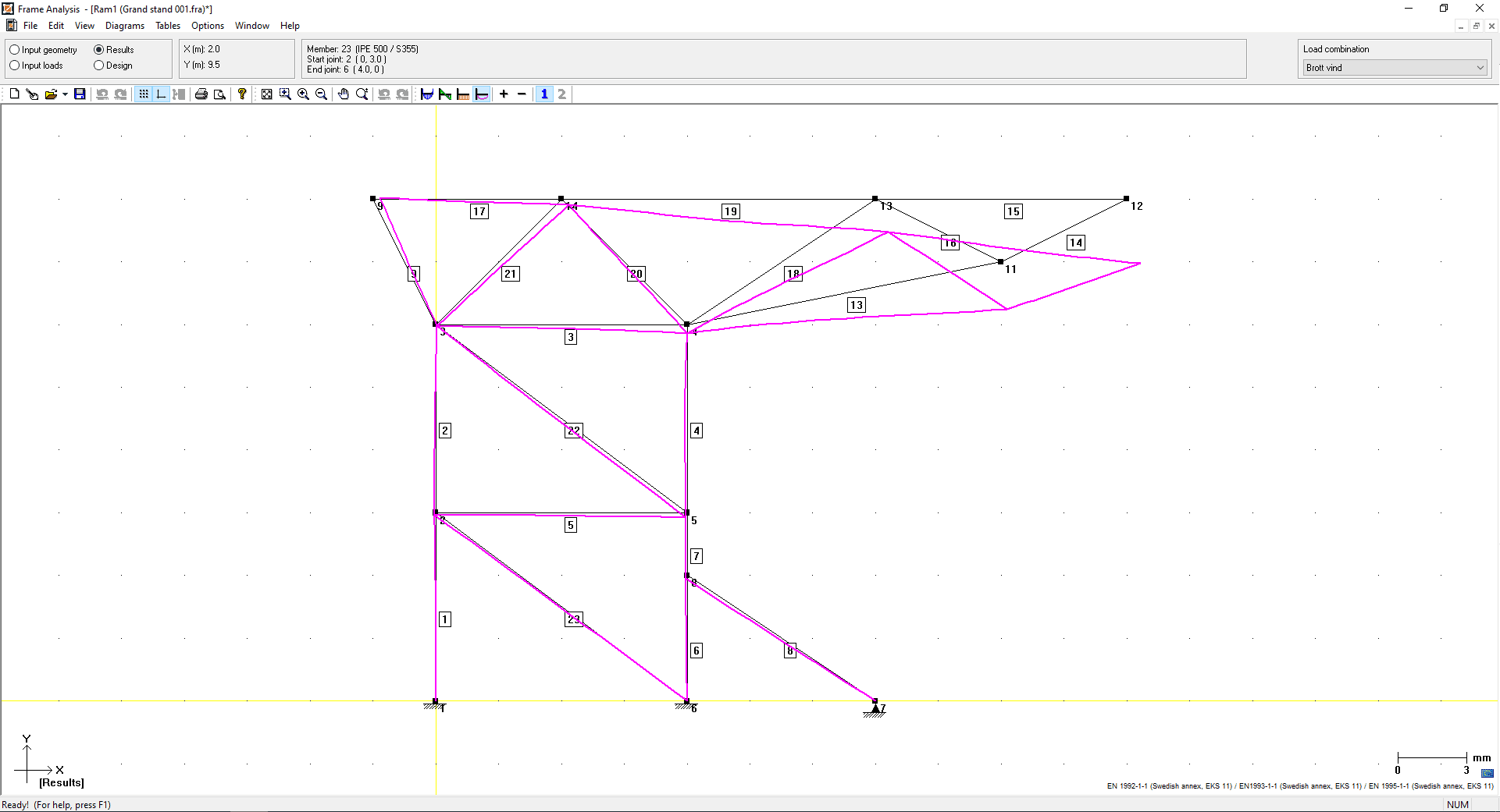
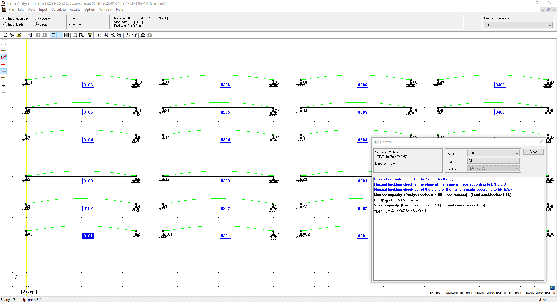
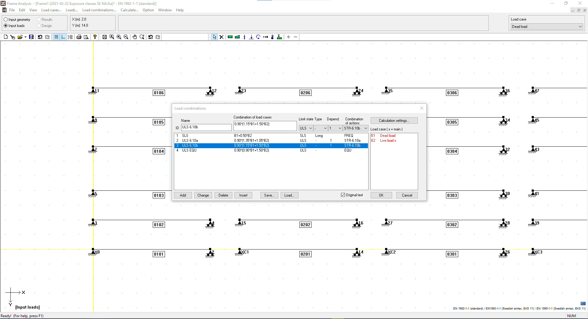
Frame analysis for plane structures with arbitrary geometry can be analysed according to the 1st or 2nd order theory with the WIN-Statik structural engineering software. With the concrete, steel, or timber modules a utilisation check can then performed for both the ultimate limit state and the serviceability limit state.
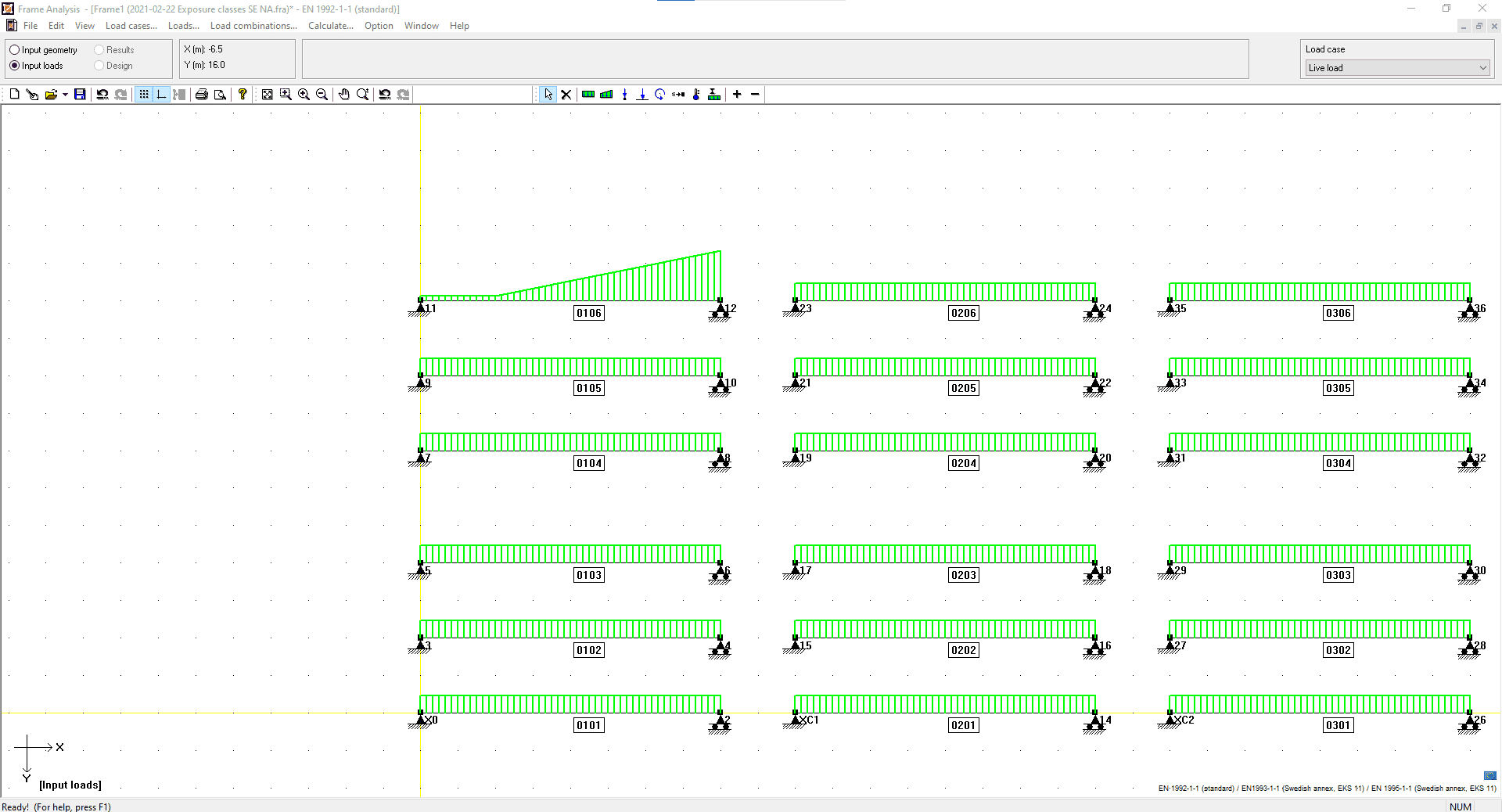
Geometry is easily created through a point and click interface, or for common structures, the parametric Geometry & Loading module can be used. Standard steel, concrete and timber sections can be found in the database, or you can define parametric sections.
A structure can then be designed according to Eurocode. Instability is also considered, you can define buckling lengths or by the 2nd order moments. With the Concrete Module a cracked section analysis considering creep and shrinkage can also be performed.
Watch a Frame Analysis Webinar
WIN-Statik Wiki – Frame Analysis Info
Frame Analysis executes the frame calculations with the finite element method where the displacement method is used to determine displacements and stresses for the whole structure by using stiffness-relations for the individual members.
The construction is divided into members and joints. The joints are those points where the members are connected. The joint conception can however be perceived in a more strict mathematical meaning, as a discreet point in the pattern that describes the structure.
The members of the construction are first being analysed and general relations between forces and displacements of the joints are being set up, these are the stiffness relations for the members. The demands of continuity and equilibrium in the joints can then be formulated with matrix-expressions and the result will be a connection between joint forces and joint displacements for the whole construction, which is the stiffness-relation of the system. The connection can generally be written in matrix-form as:
- K a = f
Where
- K is a global stiffness-matrix
- a is joint displacements
- f contains the joint forces.
The course of the calculation can be summarised as:
- Define the problem, divide the structure into beam-members and joints and initiate support as boundary conditions.
- Form member equations, i.e. connections between forces and displacements for separate members.
- Assemble; this means that the member equations are being put into the equilibrium relations for the joints, which results in an equation system for the whole structure.
- The equation system is being solved with consideration to current boundary conditions. At this the joint displacements and the reaction forces will be known.
- Member equations and the now known displacements determine the member forces.
Consideration is taken to the alteration in the forces of the members, caused by deformation of the structure, when using the second order theory.
Full technical details and the theory behind the Frame Analysis module can be found on the WIN-Statik Wiki by clicking here.
Why wait? Click to get an automated, 2 x week free trial of WIN-Statik, and get started today!
Calculations can be performed according to:
Euro Code
Danish national annex
Finnish national annex
Norwegian national annex
Swedish national annex
British national annex
WIN-Statik Blog
Introducing Simplex Foundation Design Software
StruSoft is delighted to announce the release of Simplex Foundation, a brand-new, cloud-based software designed to streamline foundation design. This intuitive 2D tool delivers [...]
Free structural analysis software for students 2024
You’re an ambitious student eager to dive into structural engineering. We’re here to help you in your journey as your partner in structural analysis [...]
How to choose the best structural analysis software for your projects in 2024
Structural analysis plays a crucial role in the design and construction of any building or infrastructure project. It entails utilizing specialized software to model [...]
