


Powerful, but easy-to-use, structural engineering software for common design tasks.
Powerful, but easy-to-use, structural engineering software for common design tasks.
Frame Analysis
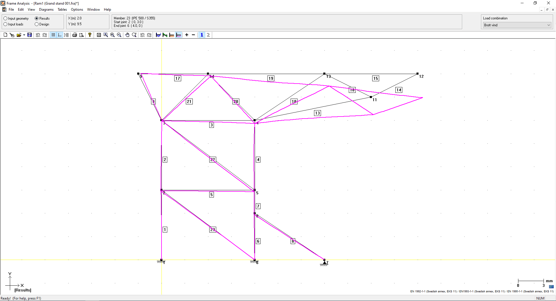
Frame analysis for plane structures with arbitrary geometry can be analysed according to the 1st or 2nd order theory with the WIN-Statik structural engineering software. With the concrete, steel, or timber modules a utilisation check can then performed for both the ultimate limit state and the serviceability limit state.
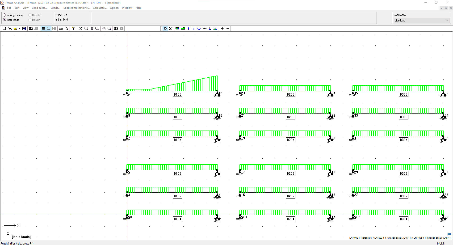
Geometry is easily created through a point and click interface, or for common structures, the parametric Geometry & Loading module can be used. Standard steel, concrete and timber sections can be found in the database, or you can define parametric sections.
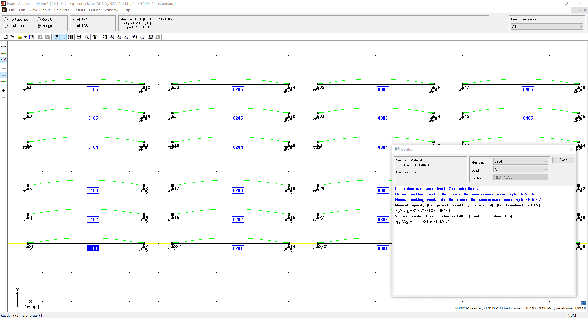
A structure can then be designed according to Eurocode. Instability is also considered, you can define buckling lengths or by the 2nd order moments. With the Concrete Module a cracked section analysis considering creep and shrinkage can also be performed.
Watch a Frame Analysis Webinar
WIN-Statik Wiki – Frame Analysis Info
Frame Analysis executes the frame calculations with the finite element method where the displacement method is used to determine displacements and stresses for the whole structure by using stiffness-relations for the individual members.
The construction is divided into members and joints. The joints are those points where the members are connected. The joint conception can however be perceived in a more strict mathematical meaning, as a discreet point in the pattern that describes the structure.
The members of the construction are first being analysed and general relations between forces and displacements of the joints are being set up, these are the stiffness relations for the members. The demands of continuity and equilibrium in the joints can then be formulated with matrix-expressions and the result will be a connection between joint forces and joint displacements for the whole construction, which is the stiffness-relation of the system. The connection can generally be written in matrix-form as:
- K a = f
Where
- K is a global stiffness-matrix
- a is joint displacements
- f contains the joint forces.
The course of the calculation can be summarised as:
- Define the problem, divide the structure into beam-members and joints and initiate support as boundary conditions.
- Form member equations, i.e. connections between forces and displacements for separate members.
- Assemble; this means that the member equations are being put into the equilibrium relations for the joints, which results in an equation system for the whole structure.
- The equation system is being solved with consideration to current boundary conditions. At this the joint displacements and the reaction forces will be known.
- Member equations and the now known displacements determine the member forces.
Consideration is taken to the alteration in the forces of the members, caused by deformation of the structure, when using the second order theory.
Full technical details and the theory behind the Frame Analysis module can be found on the WIN-Statik Wiki by clicking here.
Why wait? Click to get an automated, 2 x week free trial of WIN-Statik, and get started today!
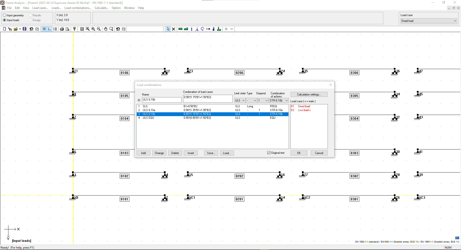
Calculations can be performed according to:
 Euro Code
- Danish national annex
- Finnish national annex
- Norwegian national annex
- Swedish national annex
- British national annex
WIN-Statik Blog

Meet the WIN-Statik Product Owner | Interview with Stefan Åberg
Have you been curious about how the software development started for our structural engineering software in Sweden? WIN-Statik was the first program developed for [...]
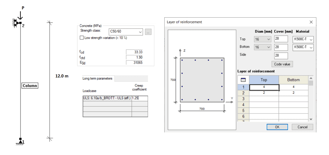
Buckling of Concrete | WIN-Statik Tips & Tricks
In a previous WIN-Statik Tips & Tricks post, we explained three methods for calculating the buckling of concrete according to EC2. These were the [...]
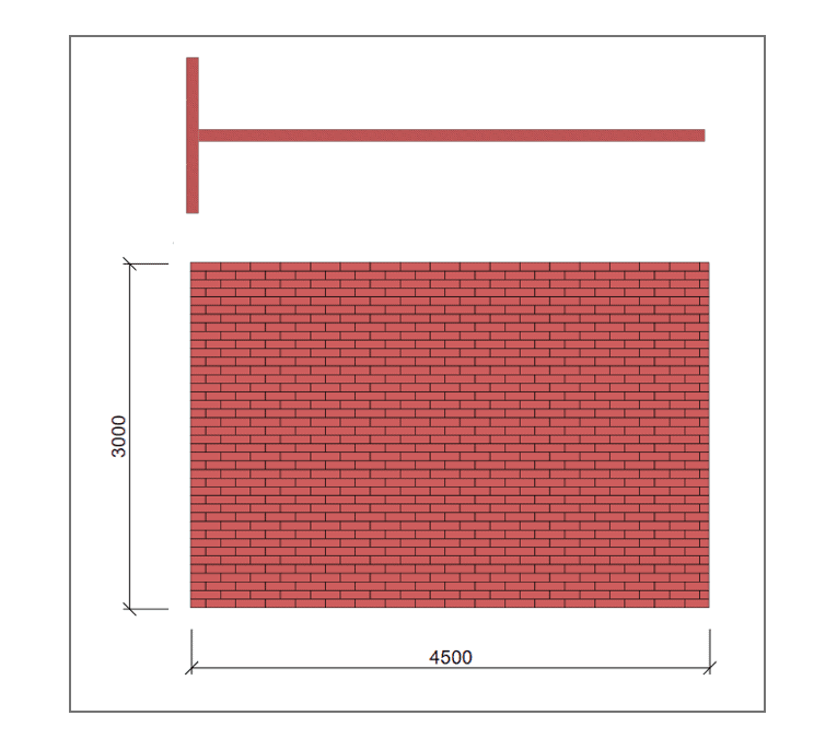
Masonry Walls as Stabilisation – A Quick Design Guide
In Sweden, the Masonry Wall is mostly used as a shell wall, i.e. as climate protection. In our neighbouring countries, on the other hand, [...]

Bio: Panos has worked for over 5 years as a structural engineer before joining StruSoft in 2025, using WIN-Statik and FEM-Design in his daily practise. Panos ...show more understands the practical needs of todays customers and will help them solve their daily problems with any StruSoft software. Feel free to contact Panos if you need any technical assistance or would like a training or a demo of our structural software. show less

Bio: Mikkel is responsible for the sales of all our structural software in Denmark. With a background in civil engineering and hands-on experience using FEM-Design for ...show more large-scale projects, he understands the challenges engineers face. Mikkel’s goal is to help Danish companies find the right structural software solutions to optimize their projects and meet their specific needs. show less

Bio: Marek Krawczyk is the Country Manager for Poland at StruSoft. As a structural engineer, he has more than ten years of international experience, working on ...show more various projects in Europe, the UK, the USA and Asia. He joined StruSoft in 2022 to strengthen our presence in Poland and support the StruSoft software Users in the local market. show less

Bio: Ciprian Tibea is the Sales Manager for Baltics & Romania and has been with StruSoft since 2018. Ciprian has a PhD in Civil Engineering (Ultra ...show more High Performance Concrete Subjected to Shear Action) and a Masters Degree in Entrepreneurship and Business Administration. Prior to StruSoft, Ciprian was working as a research engineer for Consolis for 6 years and for 1 year with a local company in Romania working on structural design projects with advanced Finite Element Software (Diana and Atena). Ciprian is your main Structural Sales contact for markets outside Europe, the Baltics and Romania. Please feel free to get in touch. show less

Bio: Mohsen Ghaemi is the Hungarian Manager for StruSoft in our Structural Business Unit. He has a PhD in Structural Civil Engineering (Topology optimisation). Mohsen has ...show more been with StruSoft since 2002 and has more than 20 years of experience with the FEM-Design software and its development, as well as in customer relationships and sales. Please feel free to get in touch with Mohsen directly. show less

Bio: Victor is Customer Success Engineer at Strusoft situated at our Gothenburg office where he works in close contact with our customers to help them use ...show more our software in the best way possible. He has a background as a structural engineer with many years of hands-on experience of using FEM-Design and WIN-Statik in his day-to-day work for large and small projects alike. Please feel free to contact Victor if you need guidance in FEM-Design, are interested in a demonstration or have any general questions. show less

Bio: Jan Wróbel has over 6 years prior experience before joining StruSoft working as a structural engineer, using FEM-Design and WIN-Statik in his daily practice. His ...show more international project work has equipped him with broad technical knowledge and understanding of various design standards and client needs. He is now focusing on technical support for Polish customers. Feel free to contact Jan for any assistance with StruSoft's structural software or any other structural engineering questions! show less

Bio: Fredrik Lagerström MSc has 8 years prior experience before joining StruSoft working as a civil engineer using FEM-Design, WIN-Statik & PRE-Stress in his daily practice. ...show more In 2011 Fredrik joined StruSoft as a Technical Sales and Education Manager. Fredrik works closely with both Sales and Development to get feedback directly from our Swedish Customers to in turn help our Developers to implement the requested new features in an accurate way. Please feel free to get in touch with Fredrik if you require any technical help or support with our structural software. show less

Bio: Shahram Omary is an account manager at Matrix Software, the Dutch affiliate of StruSoft, specializing in structural software solutions for the Dutch construction sector. With ...show more a strong technical foundation in civil engineering and a master’s degree in Construction Management and Engineering from TU Delft, Shahram combines academic insight with practical industry experience. His background spans roles in design, preparation/planning, and engineering consultancy firms. Shahram is passionate about digitalization and innovation in structural design, striving to deliver tailored software solutions that align with clients' technical and business goals. Currently, he is responsible for market strategies based on market analyses in the Dutch market. In parallel, he also contributes to the marketing aspects related to the current promotion of the software packages, including FEM-Design, in collaboration with the marketing team. show less

Bio: Anders Nilsen joined StruSoft in 2019 and starting of as a Sales Manager in Denmark. In 2024 Anders took on additional responsibilities as Head of ...show more Sales in Denmark, The Baltics, Hungary, Romania, Poland, UK & Ireland in the structural business unit of StruSoft. Anders has a background as a civil engineer with lots of practical experience in all our structural software. show less