When structural elements such as beams or decks span more than 6-8 meters, it is common that vibrations in the serviceability limit state are the dimensioning load case. There are basically two ways to assess the vibrational comfort of a structure: –
• Minimum requirement for the natural frequencies, e.g. 8 Hz.
• Minimum requirement for the accelerations, e.g. 0.2 % of gravity.
Requirements for the natural frequencies are based on a rule-of-thumb and can be misleading. The only argument for using a requirement for the natural frequency is, that it is simpler to apply. Using requirements for the accelerations have several benefits, which are shown in Figure 1.
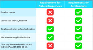
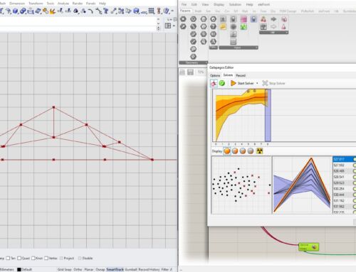
Figure 1. Benefits of using requirements for the acceleration compared to requirements for the natural frequencies
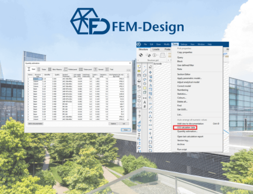
While simple estimates of the accelerations can be obtained by hand, they are often still conservative compared to a more detailed analysis, e.g. a footfall analysis in FEM-Design.
Benefits of Footfall Analysis
• Accurate calculation of accelerations for a cost-effective structural design.
• Unnecessary extra material in structural elements is minimized.
• Easy to optimise the structure by changing the size of the beams and deck elements in the model.
Self Excitation Method
For most structures, the method “Self excitation” is sufficient to determine the response for people walking on the structure. For more info on the different methods in FEM-Design see here: https://wiki.fem-design.strusoft.com/xwiki/bin/view/Main/
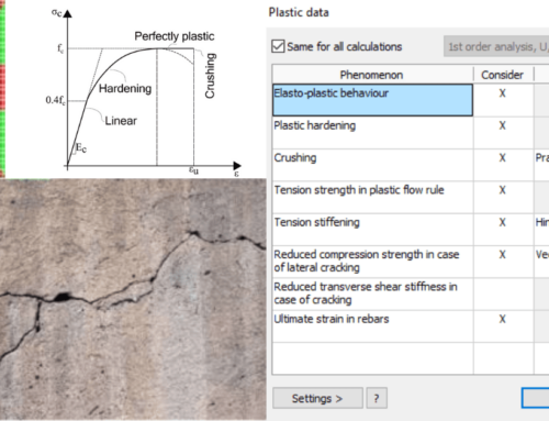
Input Parameters
Most of the input parameters are pre-set by FEM-Design and will be sufficient in most cases. he parameters to look careful at are: –
• Damping factor, which is material specific and obtained from codes or measurements.
• Effective number of people, which is assessed by the structural engineer.
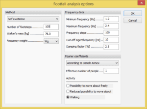
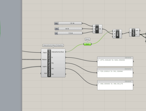
Figure 2. Input parameters for footfall analysis in FEM-Design
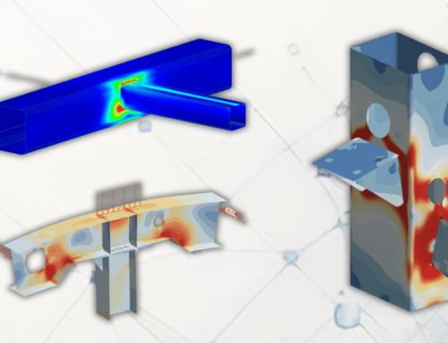
The results of a foot analysis are shown in Figure 4. The main results are the distribution of accelerations, which show the location of the largest accelerations in the structure. In Figure 4 (right) the details of the point with the largest accelerations is shown as Accelerations vs. Walking frequency.
Case Summary – School Project
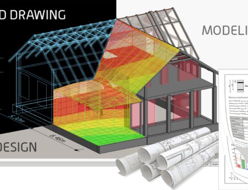
In the design phase of a school project the design engineer finds relatively low natural frequencies in some areas of the structure. One location is the school yard, which is located on top of a hall. The structure consist of TTD deck with spans more than 20 m. The first natural frequency of the structure is calculated to be 3.0 Hz. The design engineer chooses to have a detailed finite element model prepared, in which the vibrational comfort is assessed.
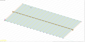
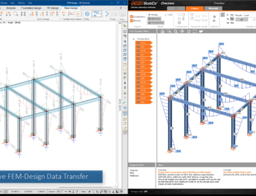
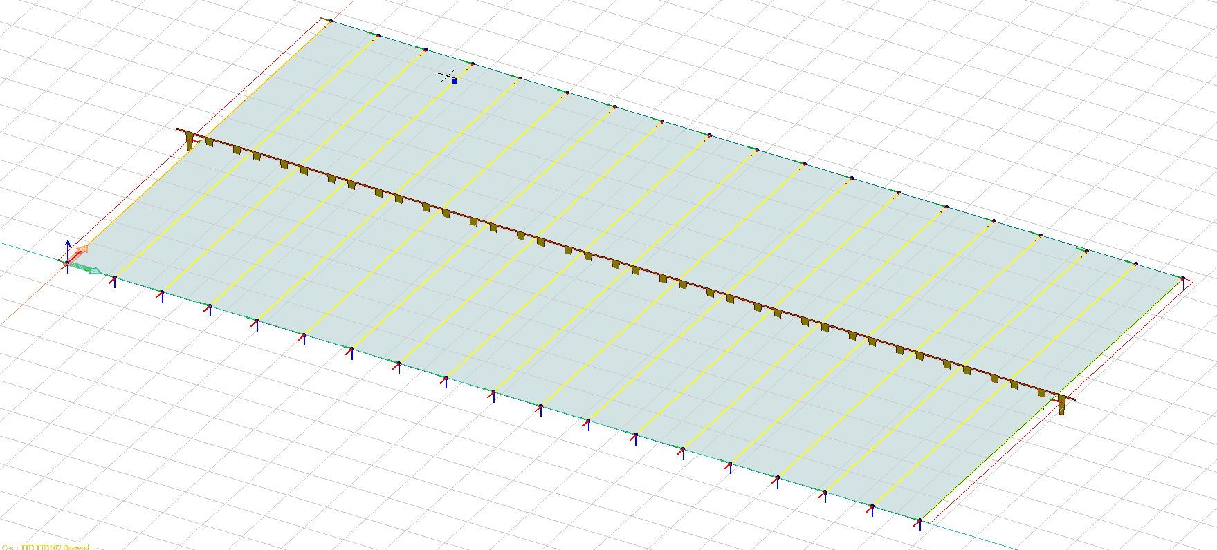
Figure 3. FEM-Design model of TTD deck
The analysis is performed in FEM-Design using footfall analysis to calculate the accelerations with dynamic loads from people walking. Appling the vibration criteria for general offices in ISO 10137 or EN 1990 DK NA (which both are considered conservative) the vibrational comfort of the structure is found to be excellent. The main reason for this is the large mass of structure.
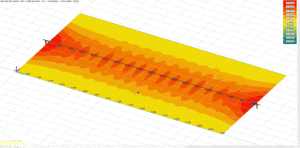
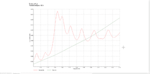
Figure 4 . Results of the footfall analysis. Left: Distribution of accelerations on the structure. Right: Acceleration as a function of the walking frequencies in the point with maximum acceleration
If the Design Engineer had omitted the detailed dynamic analysis and chased a natural frequency of e.g. 8 Hz, it would have resulted in large overconsumptions of building materials and possibly design changes, which would have resulted in an increase in both cost and CO2 footprint or the construction developer.